Nissan Sentra. Instruction — part 289
DLK-272
< DTC/CIRCUIT DIAGNOSIS >
[WITHOUT INTELLIGENT KEY SYSTEM]
KEYFOB BATTERY AND FUNCTION
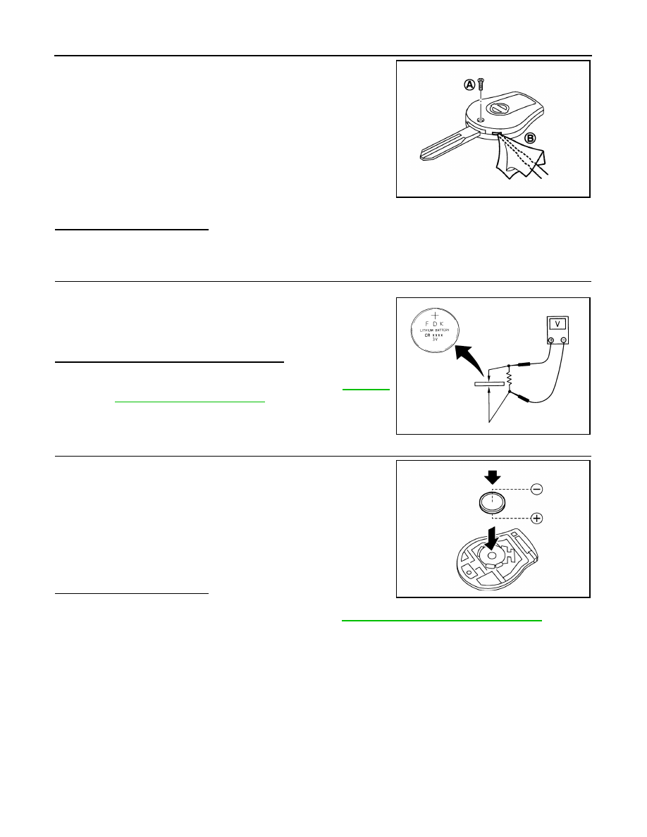
1. Remove the screw (A).
2. Insert a small screwdriver into the slit of the corner (B) and twist
it to separate the upper part from the power part. Use a cloth to
protect the casing.
CAUTION:
• Do not touch the circuit board or battery terminal.
• The keyfob is water-resistant. However, if it does get wet,
immediately wipe it dry.
3. Remove the keyfob battery.
CAUTION:
• Keep dirt, grease, and other foreign materials off the elec-
trode contact area.
4. Visually inspect keyfob internal components.
Is the inspection result normal?
YES
>> GO TO 3
NO
>> Repair or replace malfunctioning parts.
3.
CHECK KEYFOB BATTERY
Check by connecting a resistance (approximately 300
Ω) so that the
current value becomes about 10 mA.
Is the measurement value within specification?
YES
>> Keyfob battery is OK. Check remote keyless entry
receiver. Refer to
.
NO
>> GO TO 4
4.
REPLACE KEYFOB BATTERY
1. Replace the keyfob battery with a new one (CR1620 or equiva-
lent).
CAUTION:
• When replacing battery, keep dirt, grease, and other for-
eign materials off the electrode contact area.
• Make sure that the + side faces the bottom of the case.
2. Align the tips of the upper and lower parts, and then push them
together until it is securely closed.
3. After replacing the battery, check that all keyfob functions work
properly.
Is the inspection result normal?
YES
>> Keyfob is OK.
NO
>> Check remote keyless entry receiver. Refer to
DLK-268, "Component Function Check"
ALKIA2301ZZ
Standard
: Approx. 2.5 - 3.0V
OCC0607D
ALKIA2302ZZ

HORN FUNCTION
DLK-273
< DTC/CIRCUIT DIAGNOSIS >
[WITHOUT INTELLIGENT KEY SYSTEM]
C
D
E
F
G
H
I
J
L
M
A
B
DLK
N
O
P
HORN FUNCTION
Description
INFOID:0000000009756591
Perform answer-back for each operation with horn.
Component Function Check
INFOID:0000000009756592
1.
CHECK FUNCTION
1. Select HORN in “ACTIVE TEST” mode with CONSULT.
2. Check the horn operation.
Is the operation normal?
YES
>> Inspection End.
NO
>> Refer to
DLK-273, "Diagnosis Procedure"
.
Diagnosis Procedure
INFOID:0000000009756593
Regarding Wiring Diagram information, refer to
.
1.
CHECK HORN FUNCTION
Check horn function with horn switch.
Does the horn sound?
YES
>> GO TO 2
NO
>> Refer to
.
2.
CHECK HORN RELAY POWER SUPPLY
1. Turn ignition switch ON.
2. Perform “ACTIVE TEST” (“HORN”) with CONSULT.
3. Using an oscilloscope or analog voltmeter to check voltage between IPDM E/R connector and ground.
Is the inspection result normal?
YES
>> Repair or replace open harness between IPDM E/R and horn relay.
NO
>> GO TO 3
3.
CHECK HORN RELAY CIRCUIT
1. Turn ignition switch OFF.
2. Disconnect IPDM E/R and horn relay connector.
3. Check continuity between IPDM E/R harness connector and horn relay harness connector.
4. Check continuity between IPDM E/R harness connector and ground.
Test item
Description
HORN
ON
Horn relay
ON (for 20 ms)
IPDM E/R
Ground
Test item
Voltage (V)
(Approx.)
Connector
Terminal
E46
48
Ground
HORN
ON
Battery voltage
→ 0 → Battery voltage
Other than above
Battery voltage
IPDM E/R
Horn relay
Continuity
Connector
Terminal
Connector
Terminal
E46
48
H-1
1
Yes

DLK-274
< DTC/CIRCUIT DIAGNOSIS >
[WITHOUT INTELLIGENT KEY SYSTEM]
HORN FUNCTION
Is the inspection result normal?
YES
>> GO TO 4
NO
>> Repair or replace harness.
4.
CHECK INTERMITTENT INCIDENT
GI-39, "Intermittent Incident"
Is the inspection result normal?
YES
>> Replace IPDM E/R. Refer to
PCS-58, "Removal and Installation"
NO
>> Repair or replace the malfunctioning part.
IPDM E/R
Ground
Continuity
Connector
Terminal
E46
48
Ground
No

TRUNK LID OPENER ACTUATOR
DLK-275
< DTC/CIRCUIT DIAGNOSIS >
[WITHOUT INTELLIGENT KEY SYSTEM]
C
D
E
F
G
H
I
J
L
M
A
B
DLK
N
O
P
TRUNK LID OPENER ACTUATOR
Component Function Check
INFOID:0000000009756594
1.
CHECK FUNCTION
1. Select INTELLIGENT KEY of BCM using CONSULT.
2. Select TRUNK/GLASS HATCH in ACTIVE TEST mode.
3. Touch OPEN to check that it works normally.
Is the inspection result normal?
YES
>> Trunk lid opener actuator is OK.
NO
>> Refer to
DLK-275, "Diagnosis Procedure"
Diagnosis Procedure
INFOID:0000000009756595
Regarding Wiring Diagram information, refer to
.
1.
CHECK TRUNK LID OPENER INPUT SIGNAL
1. Turn ignition switch OFF.
2. Disconnect trunk lid opener assembly connector.
3. Check voltage between trunk lid opener assembly harness connector and ground.
Is the inspection result normal?
YES
>> GO TO 3.
NO
>> GO TO 2.
2.
CHECK TRUNK LID OPENER ACTUATOR CIRCUIT
1. Disconnect BCM connector.
2. Check continuity between BCM harness connector and trunk lid opener assembly harness connector.
3. Check continuity between BCM harness connector and ground.
Is the inspection result normal?
YES
>> Replace BCM. Refer to
BCS-126, "Removal and Installation"
.
NO
>> Repair or replace harness.
3.
CHECK TRUNK LID OPENER ACTUATOR GROUND CIRCUIT
Check continuity between trunk lid opener assembly harness connector and ground.
(+)
(–)
Condition
Voltage
(Approx.)
Trunk lid opener assembly
Connector
Terminal
B59
3
Ground
Trunk lid opener switch is ON
12 V
BCM
Trunk lid opener assembly
Continuity
Connector
Terminal
Connector
Terminal
B57
55
B59
3
Yes
BCM
Ground
Continuity
Connector
Terminal
B57
55
No
Нет комментариевНе стесняйтесь поделиться с нами вашим ценным мнением.
Текст