Nissan Sentra. Instruction — part 286
DLK-260
< DTC/CIRCUIT DIAGNOSIS >
[WITHOUT INTELLIGENT KEY SYSTEM]
KEY CYLINDER SWITCH
KEY CYLINDER SWITCH
Description
INFOID:0000000009756568
When the mechanical key is inserted and turned into the front door lock key cylinder switch LH, the switch
transmits the LOCK or UNLOCK signal directly to the BCM.
Component Function Check
INFOID:0000000009756569
1.
CHECK DOOR KEY CYLINDER SWITCH INPUT SIGNAL
Check KEY CYL UN-SW, KEY CYL UN-SW in “DATA MONITOR” mode for “POWER DOOR LOCK SYSTEM”
with CONSULT. Refer to
DLK-221, "DOOR LOCK : CONSULT Function (BCM - DOOR LOCK)"
.
Is the inspection result normal?
YES
>> Key cylinder switch is OK.
NO
>> Refer to
DLK-260, "Diagnosis Procedure"
.
Diagnosis Procedure
INFOID:0000000009756570
Regarding Wiring Diagram information, refer to
.
1.
CHECK DOOR KEY CYLINDER SWITCH INPUT SIGNAL
1. Turn ignition switch ON.
2. Check voltage between BCM connector and ground.
Is the inspection result normal?
YES
>> Front door lock key cylinder switch LH is OK.
NO
>> GO TO 2
2.
CHECK DOOR KEY CYLINDER SWITCH GROUND CIRCUIT
1. Turn ignition switch OFF.
2. Disconnect front door lock key cylinder switch LH connector.
3. Check continuity between front door lock key cylinder switch LH connector and ground.
Is the inspection result normal?
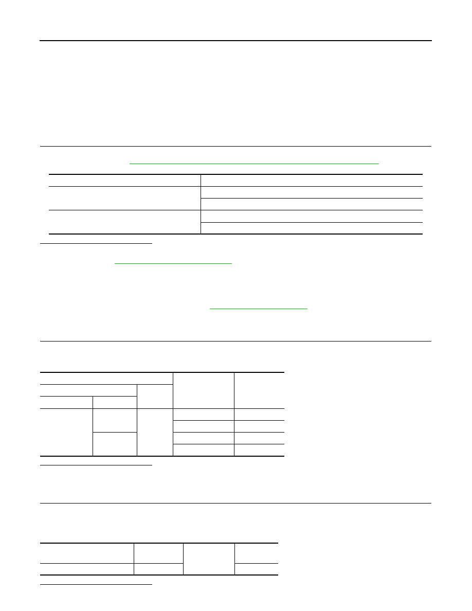
Monitor item
Condition
KEY CYL LK-SW
Lock
: ON
Neutral / Unlock
: OFF
KEY CYL UN-SW
Unlock
: ON
Neutral / Lock
: OFF
Terminals
Key position
Voltage (V)
(Approx.)
(+)
(–)
BCM connector
Terminal
M21
8
Ground
Lock
0
Neutral / Unlock
5
7
Unlock
0
Neutral / Lock
5
Front door lock key cylinder
switch LH connector
Terminal
Ground
Continuity
D9
4
Yes
KEY CYLINDER SWITCH
DLK-261
< DTC/CIRCUIT DIAGNOSIS >
[WITHOUT INTELLIGENT KEY SYSTEM]
C
D
E
F
G
H
I
J
L
M
A
B
DLK
N
O
P
YES
>> GO TO 3
NO
>> Repair or replace harness.
3.
CHECK DOOR KEY CYLINDER SIGNAL CIRCUIT
1. Disconnect BCM connector M21.
2. Check continuity between front door lock key cylinder switch LH connector and BCM connector M21.
3. Check continuity between front door lock key cylinder switch LH connector and ground.
Is the inspection result normal?
YES
>> GO TO 4
NO
>> Repair or replace harness.
4.
CHECK DOOR KEY CYLINDER SWITCH
Check door key cylinder switch.
DLK-261, "Component Inspection"
.
Is the inspection result normal?
YES
>> Check intermittent incident. Refer to
GI-39, "Intermittent Incident"
.
NO
>> Replace front door lock key cylinder switch LH.
Component Inspection
INFOID:0000000009756571
COMPONENT INSPECTION
1.
CHECK DOOR KEY CYLINDER SWITCH
Check front door lock key cylinder switch LH.
Is the inspection result normal?
YES
>> Key cylinder switch is OK.
NO
>> Replace front door lock key cylinder switch LH.
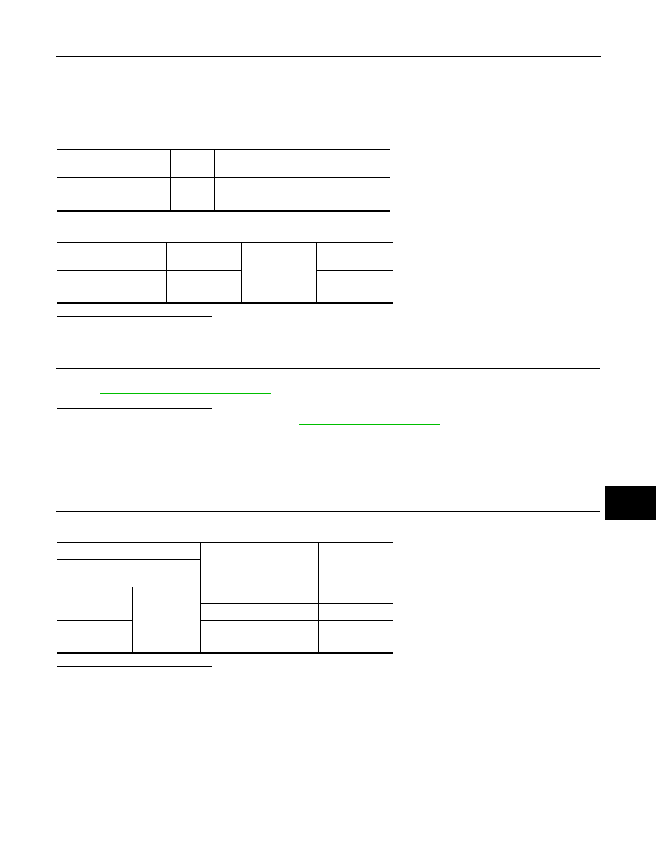
Front door lock key cylin-
der switch LH connector
Terminal
BCM connector
Terminal
Continuity
D9
6
M21
8
Yes
5
7
Front door lock key cylin-
der switch LH connector
Terminal
Ground
Continuity
D9
6
No
5
Terminal
Key position
Continuity
Front door lock key cylinder
switch LH connector
6
4
Lock
Yes
Neutral / Unlock
No
5
Unlock
Yes
Neutral / Lock
No
DLK-262
< DTC/CIRCUIT DIAGNOSIS >
[WITHOUT INTELLIGENT KEY SYSTEM]
KEY SWITCH (BCM INPUT)
KEY SWITCH (BCM INPUT)
Diagnosis Procedure
INFOID:0000000009756572
Regarding Wiring Diagram information, refer to
.
1.
CHECK KEY SWITCH INPUT SIGNAL
With CONSULT
Check key switch "KEY ON SW" in DATA MONITOR mode with CONSULT. Refer to
: CONSULT Function (BCM - DOOR LOCK)"
• When key is inserted to ignition key cylinder:
• When key is removed from ignition key cylinder:
Without CONSULT
Check voltage between BCM connector M21 terminal 37 and ground.
Is the inspection result normal?
YES
>> Key switch (insert) circuit is OK.
NO
>> GO TO 2
2.
CHECK KEY SWITCH (INSERT)
1. Turn ignition switch OFF.
2. Disconnect key switch connector.
3. Check continuity between key switch terminals.
Is the inspection result normal?
YES
>> Repair or replace harness or fuse.
NO
>> Replace key switch.
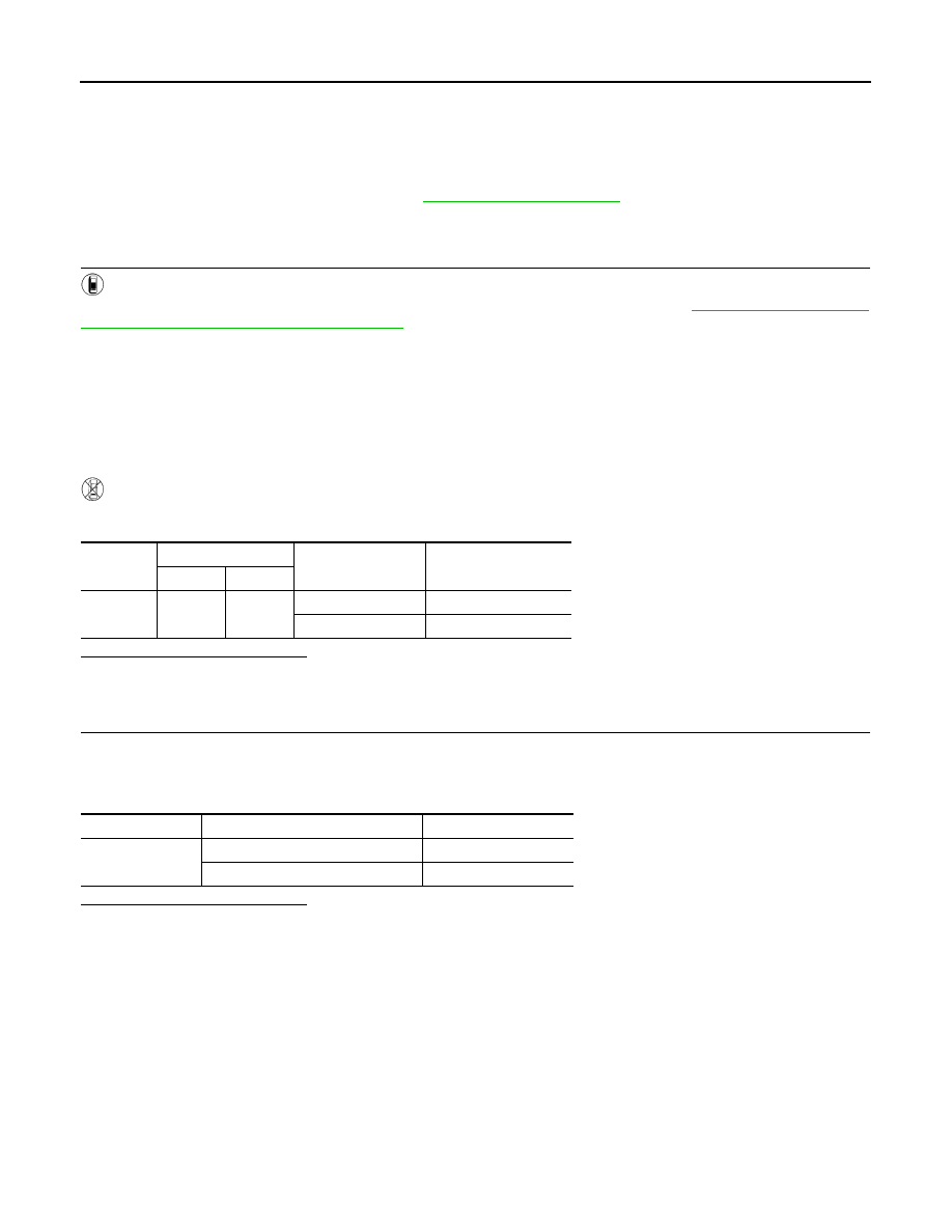
KEY ON SW
: ON
KEY ON SW
: OFF
Connector
Terminal
Condition
Voltage (V)
(+)
(–)
M21
37
Ground
Key is inserted.
Battery voltage
Key is removed.
0
Terminals
Condition
Continuity
1 – 2
Key is inserted.
Yes
Key is removed.
No
DOOR LOCK ACTUATOR
DLK-263
< DTC/CIRCUIT DIAGNOSIS >
[WITHOUT INTELLIGENT KEY SYSTEM]
C
D
E
F
G
H
I
J
L
M
A
B
DLK
N
O
P
DOOR LOCK ACTUATOR
DRIVER SIDE
DRIVER SIDE : Description
INFOID:0000000009756573
Locks/unlocks the door with the signal from BCM.
DRIVER SIDE : Component Function Check
INFOID:0000000009756574
1.
CHECK FUNCTION
1. Use CONSULT to perform Active Test (“DOOR LOCK”).
2. Touch “ALL LOCK” or “ALL UNLOCK” to check that it works normally.
Is the inspection result normal?
YES
>> Door lock actuator is OK.
NO
>> Refer to
DLK-263, "DRIVER SIDE : Diagnosis Procedure"
.
DRIVER SIDE : Diagnosis Procedure
INFOID:0000000009756575
Regarding Wiring Diagram information, refer to
.
1.
CHECK OUTPUT SIGNAL
Check voltage between BCM connector and ground.
Is the inspection result normal?
YES
>> GO TO 3
NO
>> GO TO 2
2.
CHECK DOOR LOCK ACTUATOR CIRCUIT
1. Turn ignition switch OFF.
2. Disconnect BCM and front door lock actuator driver side connector.
3. Check continuity between BCM connector and front door lock actuator driver side connector.
4. Check continuity between BCM connector and ground.
Is the inspection result normal?
YES
>> Replace front door lock actuator LH.
NO
>> Repair or replace harness.
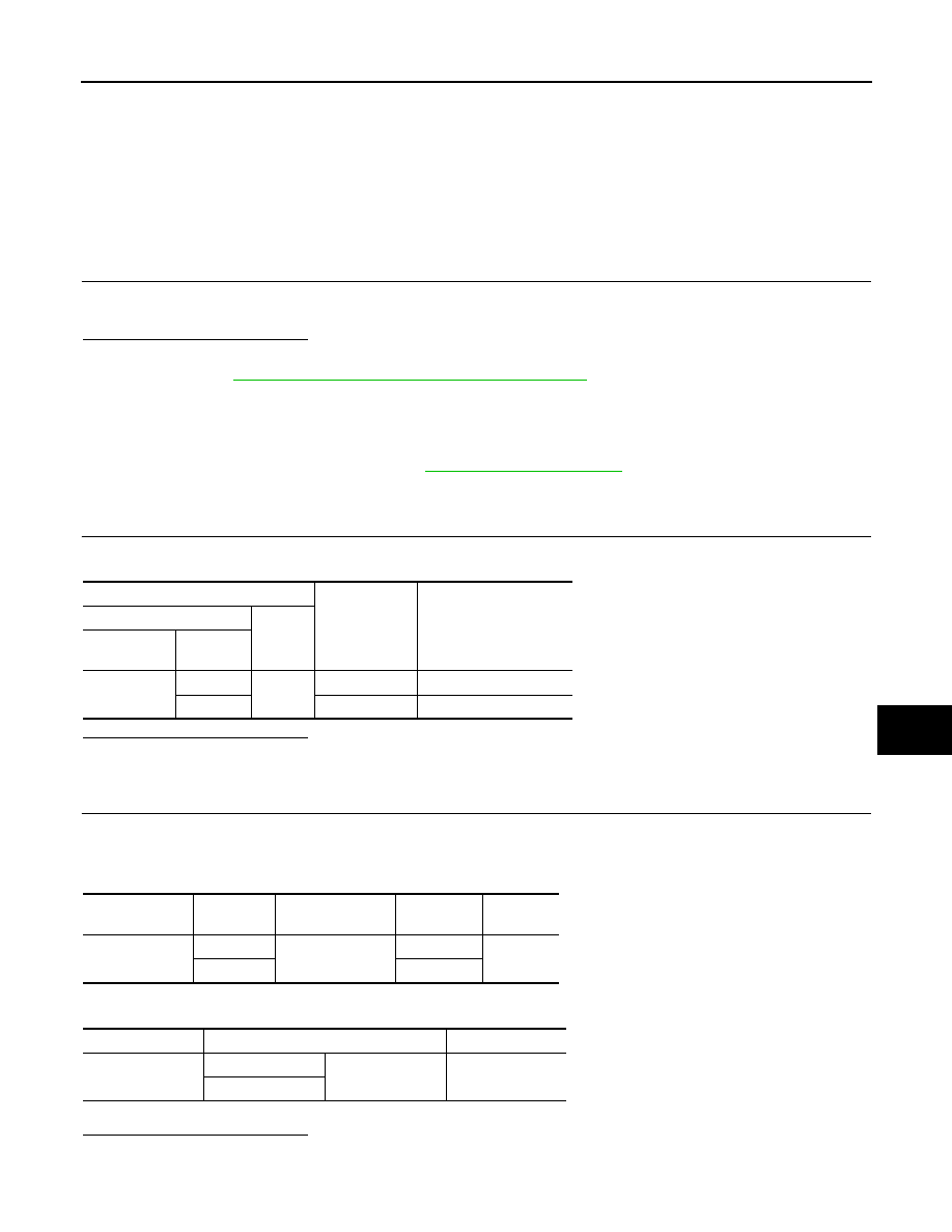
Terminals
Condition of
door lock and
unlock switch
Voltage (V)
(Approx.)
(+)
(–)
BCM
connector
Terminal
M20
64
Ground
Unlock
0
→ Battery voltage → 0
66
Lock
0
→ Battery voltage → 0
BCM connector
Terminal
Door lock actuator
connector
Terminal
Continuity
M20
64
D9
2
Yes
66
1
BCM connector
Terminal
Continuity
M20
64
Ground
No
66
Нет комментариевНе стесняйтесь поделиться с нами вашим ценным мнением.
Текст