Nissan Qashqai (2007-2010). Manual — part 555
INPUT SHAFT AND GEAR
TM-155
< DISASSEMBLY AND ASSEMBLY >
[6MT: RS6F52A]
C
E
F
G
H
I
J
K
L
M
A
B
TM
N
O
P
INPUT SHAFT AND GEAR
Exploded View
INFOID:0000000001034955
Disassembly
INFOID:0000000001034956
1.
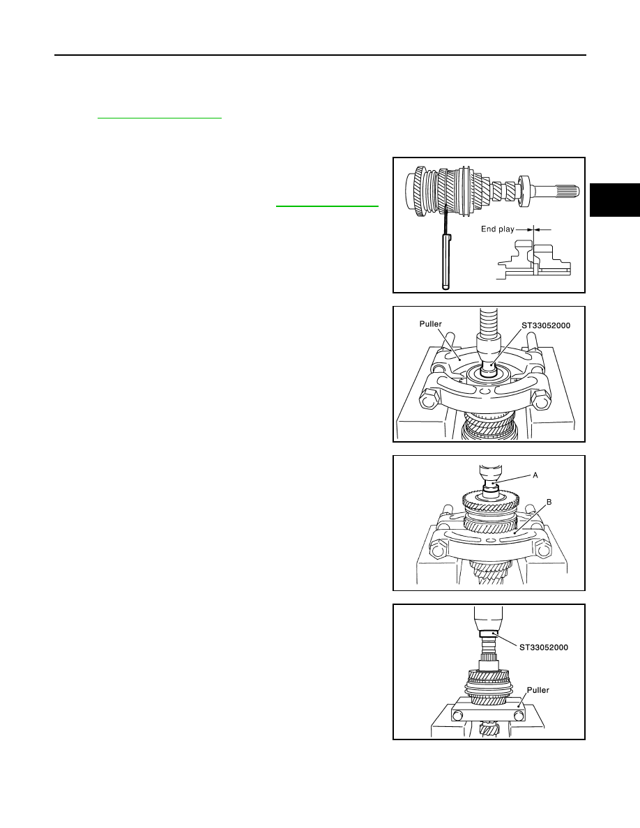
Before disassembling, measure end play for 3rd, 4th, 5th, and
6th input gears.
2.
Remove oil channel.
3.
Press out input shaft rear bearing using the drift and a puller.
4.
Remove snap ring.
5.
Press out 6th input gear, 6th needle bearing, 6th input gear
bushing, 5th-6th synchronizer hub assembly, and 5th input gear
using the drift (A) [SST: ST33052000] and a puller (B).
6.
Remove 5th needle bearing.
7.
Press out 5th input gear bushing, thrust washer, 4th input gear,
4th needle bearing, 4th input gear bushing, 3rd-4th synchronizer
hub assembly, and 3rd input gear using the drift and a puller.
8.
Remove 3rd needle bearing.
End play standard value
: Refer to
SCIA0966E
SCIA0967E
PCIB1882E
SCIA0919E
TM-156
< DISASSEMBLY AND ASSEMBLY >
[6MT: RS6F52A]
INPUT SHAFT AND GEAR
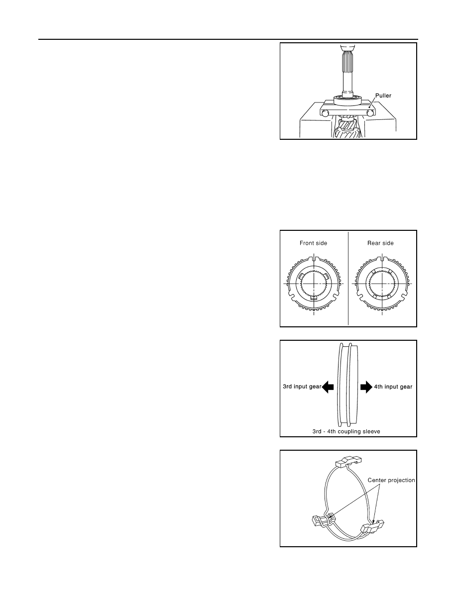
9.
Press out input shaft front bearing using a puller.
Assembly
INFOID:0000000001034957
1.
Install 3rd needle bearing to input shaft.
2.
Install 3rd input gear, 3rd inner baulk ring, 3rd synchronizer cone, and 3rd outer baulk ring to input shaft.
CAUTION:
Replace 3rd inner baulk ring, 3rd synchronizer cone, and 3rd outer baulk ring as a set.
3.
Install 3rd-4th spread springs, 3rd-4th shifting inserts, and 3rd-4th synchronizer hub onto 3rd-4th coupling
sleeve.
CAUTION:
• Be careful with orientation of 3rd-4th synchronizer hub.
• Never reuse 3rd-4th synchronizer hub and 3rd-4th cou-
pling sleeve.
• Replace 3rd-4th synchronizer hub and 3rd-4th coupling
sleeve as a set.
• Be careful with orientation of 3rd-4th coupling sleeve.
• Be sure not to hook center projection of 2 spread springs
on same shifting insert.
SCIA0920E
SCIA0921E
PCIB0799E
SCIA1083E
INPUT SHAFT AND GEAR
TM-157
< DISASSEMBLY AND ASSEMBLY >
[6MT: RS6F52A]
C
E
F
G
H
I
J
K
L
M
A
B
TM
N
O
P
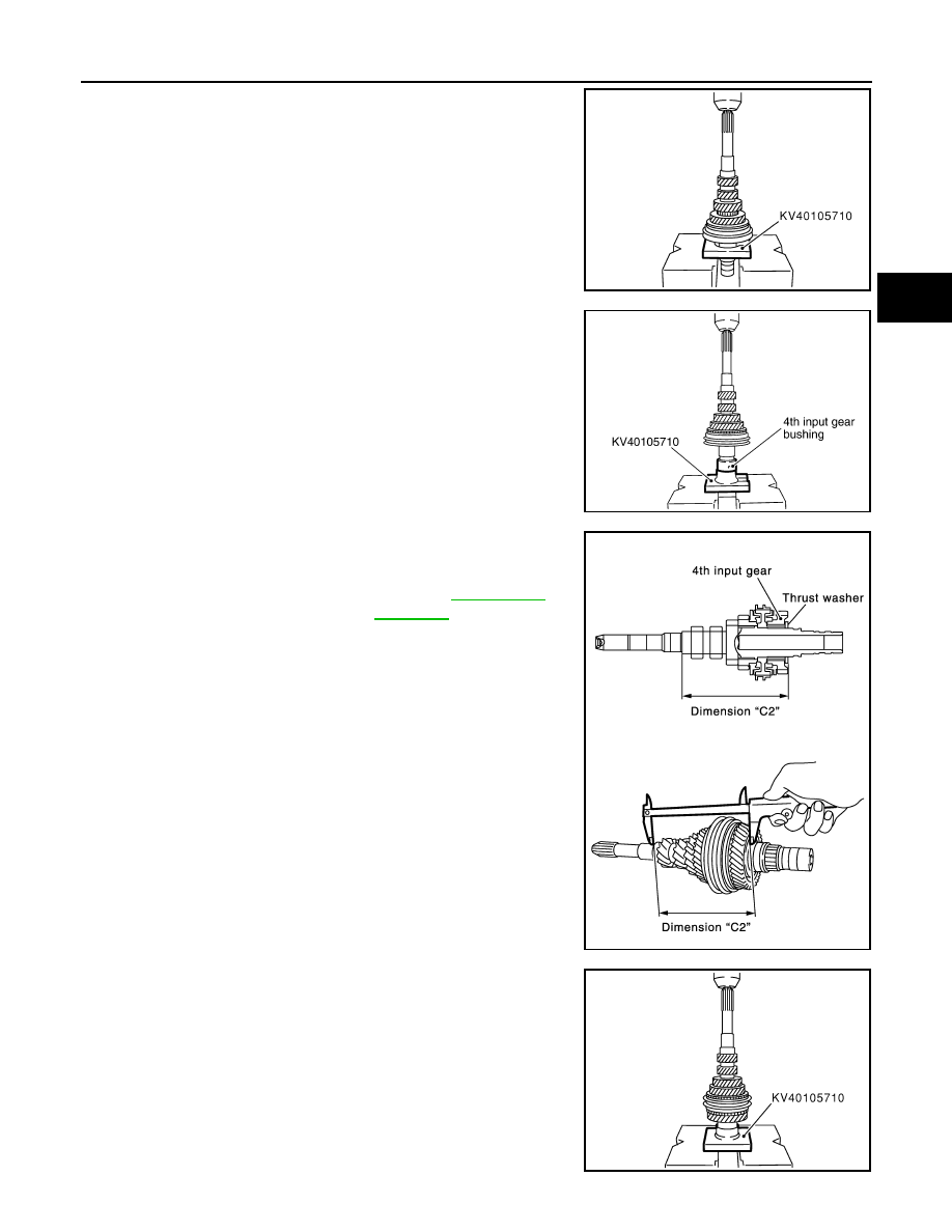
4.
Press in 3rd-4th synchronizer hub assembly using the press
stand.
CAUTION:
Align grooves of 3rd-4th shifting insert and 3rd outer baulk
ring.
5.
Press in 4th input gear bushing using the press stand.
6.
Install 4th baulk ring.
7.
Install 4th needle bearing and 4th input gear to input shaft.
8.
Select thrust washer so that dimension “C2” satisfies the stan-
dard value below. Then install thrust washer onto input shaft.
CAUTION:
Only one thrust washer can be selected.
9.
Press in 5th input gear bushing using the press stand.
CAUTION:
Never reuse 5th input gear bushing.
10. Install 5th needle bearing and 5th input gear to input shaft.
11. Install 5th baulk ring.
SCIA0922E
PCIB0800E
Standard value for dimen-
sion “C2”
: Refer to
.
SCIA0925E
SCIA0926E
TM-158
< DISASSEMBLY AND ASSEMBLY >
[6MT: RS6F52A]
INPUT SHAFT AND GEAR
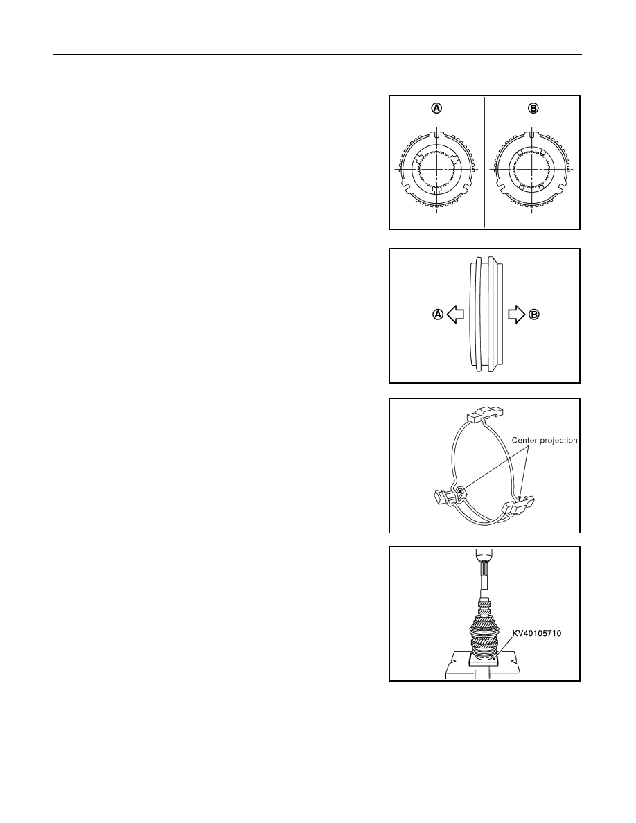
12. Install 5th-6th synchronizer hub, 5th-6th spread springs, and 5th-6th shifting inserts onto 5th-6th coupling
sleeve.
CAUTION:
• Be careful with orientation of 5th-6th synchronizer hub.
• Never reuse 5th-6th synchronizer hub and 5th-6th cou-
pling sleeve.
• Replace 5th-6th synchronizer hub and 5th-6th coupling
sleeve as a set.
• Be careful with orientation of 5th-6th coupling sleeve.
• Be sure not to hook center projection of 2 spread springs
on same shifting insert.
13. Press in 5th-6th synchronizer hub assembly using the press
stand.
CAUTION:
Align grooves of 5th-6th shifting insert and 5th baulk ring.
A
: Front side
B
: Rear side
PCIB1883E
A
: 5th input gear side
B
: 6th input gear side
PCIB1884E
SCIA1083E
SCIA0928E
Нет комментариевНе стесняйтесь поделиться с нами вашим ценным мнением.
Текст