Nissan Qashqai (2007-2010). Manual — part 383
ON BOARD DIAGNOSTIC (OBD) SYSTEM
EC-1051
< FUNCTION DIAGNOSIS >
[MR20DE (WITHOUT EURO-OBD)]
C
D
E
F
G
H
I
J
K
L
M
A
EC
N
P
O
• Freeze frame data
• 1st trip freeze frame data
• Test values
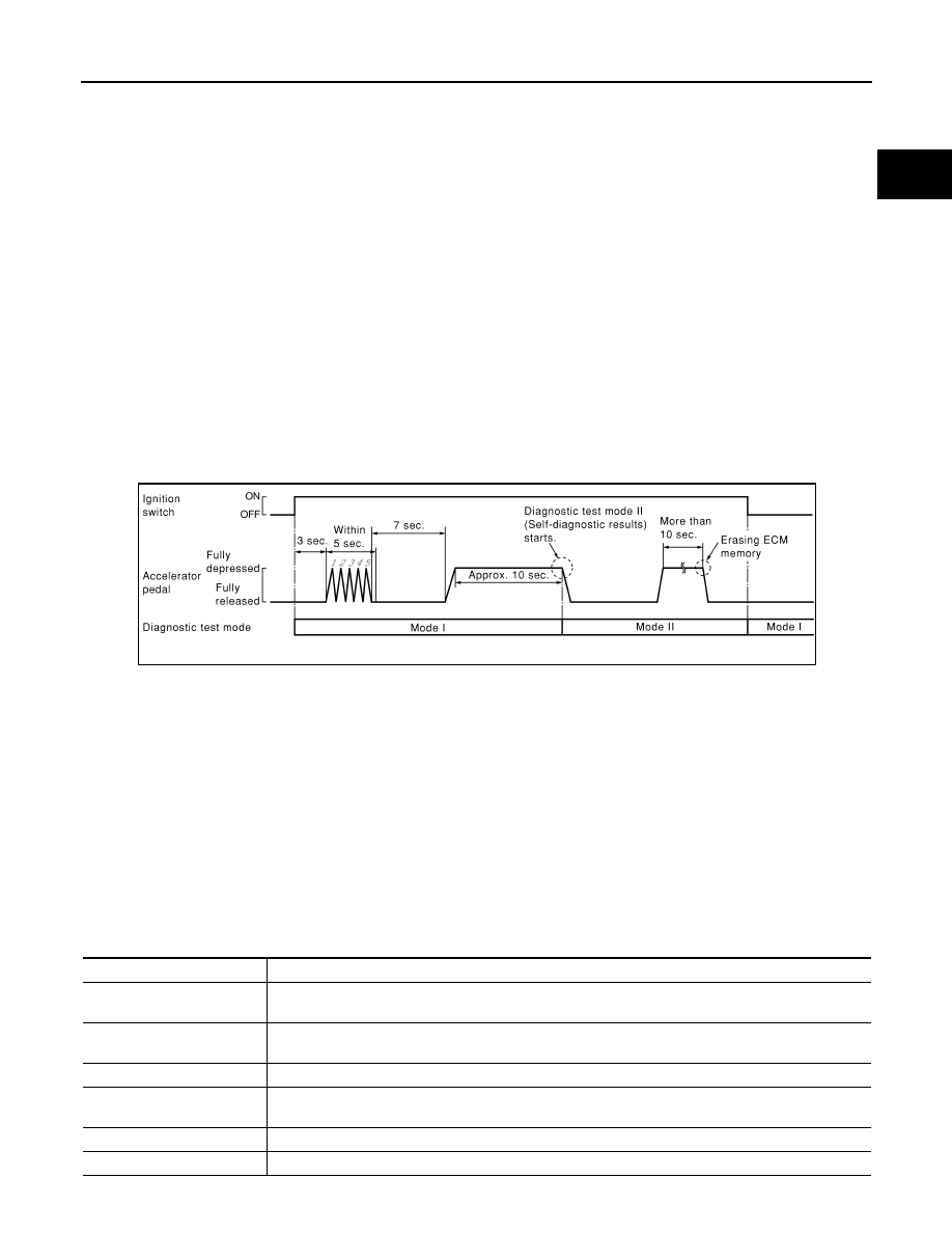
How to Switch Diagnostic Test Mode
NOTE:
• It is better to count the time accurately with a clock.
• It is impossible to switch the diagnostic mode when an accelerator pedal position sensor circuit has
a malfunction.
• Always ECM returns to Diagnostic Test Mode I after ignition switch is turned OFF.
HOW to SET DIAGNOSTIC TEST MODE II (SELF-DIAGNOSTIC RESULTS)
1.
Confirm that accelerator pedal is fully released, turn ignition switch ON and wait 3 seconds.
2.
Repeat the following procedure quickly five times within 5 seconds.
a.
Fully depress the accelerator pedal.
b.
Fully release the accelerator pedal.
3.
Wait 7 seconds, fully depress the accelerator pedal and keep it for approx. 10 seconds until the MI starts
blinking.
4.
Fully release the accelerator pedal.
ECM has entered to Diagnostic Test Mode II (Self-diagnostic results).
NOTE:
Wait until the same DTC (or 1st trip DTC) appears to confirm all DTCs certainly.
HOW to SET DIAGNOSTIC TEST MODE II (HEATED OXYGEN SENSOR 1 MONITOR)
1.
Set the ECM in Diagnostic Test Mode II (Self-diagnostic results).
Refer to “HOW to SET DIAGNOSTIC TEST MODE II (SELF-DIAGNOSTIC RESULTS)”.
2.
Start Engine.
ECM has entered to Diagnostic Test Mode II (Heated oxygen sensor 1 monitor).
HOW to ERASE DIAGNOSTIC TEST MODE II (SELF-DIAGNOSTIC RESULTS)
1.
Set ECM in Diagnostic Test Mode II (Self-diagnostic results). Refer to “HOW to SET DIAGNOSTIC TEST
MODE II (SELF-DIAGNOSTIC RESULTS)”.
2.
Fully depress the accelerator pedal and keep it for more than 10 seconds.
The emission-related diagnostic information has been erased from the backup memory in the ECM.
3.
Fully release the accelerator pedal, and confirm the DTC 0000 is displayed.
CONSULT-III Function
INFOID:0000000001094083
FUNCTION
PBIB0092E
Diagnostic test mode
Function
Work support
This mode enables a technician to adjust some devices faster and more accurately by following the in-
dications on the CONSULT-III unit.
Self-diagnostic results
Self-diagnostic results such as 1st trip DTC, DTCs and 1st trip freeze frame data or freeze frame data
can be read and erased quickly.*
Data monitor
Input/Output data in the ECM can be read.
Active test
Diagnostic Test Mode in which CONSULT-III drives some actuators apart from the ECMs and also shifts
some parameters in a specified range.
Function test
This mode is used to inform customers when their vehicle condition requires periodic maintenance.
ECU part number
ECM part number can be read.

EC-1052
< FUNCTION DIAGNOSIS >
[MR20DE (WITHOUT EURO-OBD)]
ON BOARD DIAGNOSTIC (OBD) SYSTEM
*: The following emission-related diagnostic information is cleared when the ECM memory is erased.
• Diagnostic trouble codes
• 1st trip diagnostic trouble codes
• Freeze frame data
• 1st trip freeze frame data
• Test values
ENGINE CONTROL COMPONENT PARTS/CONTROL SYSTEMS APPLICATION
X: Applicable
Item
DIAGNOSTIC TEST MODE
WORK
SUPPORT
SELF-DIAGNOSTIC RE-
SULTS
DATA
MONI-
TOR
DATA
MONI-
TOR
(SPEC)
ACTIVE
TEST
DTC*
1
FREEZE
FRAME DA-
TA*
2
ENGINE CONTROL COMP
O
N
ENT P
A
RTS
INPUT
Crankshaft position sensor (POS)
×
×
×
×
Camshaft position sensor (PHASE)
×
×
×
×
Mass air flow sensor
×
×
×
Engine coolant temperature sensor
×
×
×
×
×
Heated oxygen sensor 1
×
×
×
Heated oxygen sensor 2
×
×
×
Wheel sensor
×
×
×
×
Accelerator pedal position sensor
×
×
×
Throttle position sensor
×
×
×
Intake air temperature sensor
×
×
×
×
Knock sensor
×
EPS control unit
×
×
Refrigerant pressure sensor
×
×
Closed throttle position switch (accelerator
pedal position sensor signal)
×
×
Air conditioner switch
×
×
Park/neutral position (PNP) switch
×
×
×
Stop lamp switch
×
×
×
Battery voltage
×
×
Load signal
×
×
ENGINE CONTROL COMPONENT P
ARTS
OU
TPUT
Fuel injector
×
×
×
Power transistor (Ignition timing)
×
×
×
Throttle control motor relay
×
×
×
Throttle control motor
×
EVAP canister purge volume control sole-
noid valve
×
×
×
×
Air conditioner relay
×
×
Fuel pump relay
×
×
×
×
Cooling fan relay
×
×
×
×
Heated oxygen sensor 1 heater
×
×
×
Heated oxygen sensor 2 heater
×
×
×
Intake valve timing control solenoid valve
×
×
×
×
Calculated load value
×
×
×

ON BOARD DIAGNOSTIC (OBD) SYSTEM
EC-1053
< FUNCTION DIAGNOSIS >
[MR20DE (WITHOUT EURO-OBD)]
C
D
E
F
G
H
I
J
K
L
M
A
EC
N
P
O
*1: This item includes 1st trip DTCs.
*2: This mode includes 1st trip freeze frame data or freeze frame data. The items appear on CONSULT-II screen in freeze frame data
mode only if a 1st trip DTC or DTC is detected. For details, refer to
EC-1050, "Diagnosis Description"
.
WORK SUPPORT MODE
Work Item
*: This function is not necessary in the usual service procedure.
SELF-DIAG RESULTS MODE
Self Diagnostic Item
Regarding items of DTC and 1st trip DTC, refer to
.)
Freeze Frame Data and 1st Trip Freeze Frame Data
*: The items are the same as those of 1st trip freeze frame data.
WORK ITEM
CONDITION
USAGE
FUEL PRESSURE RELEASE
• FUEL PUMP WILL STOP BY TOUCHING “START” DUR-
ING IDLING.
CRANK A FEW TIMES AFTER ENGINE STALLS.
When releasing fuel pressure from
fuel line
IDLE AIR VOL LEARN
• THE IDLE AIR VOLUME THAT KEEPS THE ENGINE
WITHIN THE SPECIFIED RANGE IS MEMORIZED IN
ECM.
When learning the idle air volume
SELF-LEARNING CONT
• THE COEFFICIENT OF SELF-LEARNING CONTROL
MIXTURE RATIO RETURNS TO THE ORIGINAL COEF-
FICIENT.
When clearing mixture ratio self-
learning value
TARGET IDLE RPM ADJ*
• IDLE CONDITION
When setting target idle speed
TARGET IGN TIM ADJ*
• IDLE CONDITION
When adjusting target ignition tim-
ing
Freeze frame data
item*
Description
DIAG TROUBLE
CODE
[PXXXX]
• The engine control component part/control system has a trouble code, it is displayed as PXXXX. (Refer to
.)
FUEL SYS-B1
• “Fuel injection system status” at the moment a malfunction is detected is displayed.
• One mode in the following is displayed.
Mode2: Open loop due to detected system malfunction
Mode3: Open loop due to driving conditions (power enrichment, deceleration enleanment)
Mode4: Closed loop - using oxygen sensor(s) as feedback for fuel control
Mode5: Open loop - has not yet satisfied condition to go to closed loop
COOLANT TEMP [
°
C]
or [
°
F]
• The engine coolant temperature at the moment a malfunction is detected is displayed.
L-FUEL TRM-B1 [%]
• “Long-term fuel trim” at the moment a malfunction is detected is displayed.
• The long-term fuel trim indicates much more gradual feedback compensation to the base fuel schedule than
short-term fuel trim.
S-FUEL TRM-B1 [%]
• “Short-term fuel trim” at the moment a malfunction is detected is displayed.
• The short-term fuel trim indicates dynamic or instantaneous feedback compensation to the base fuel sched-
ule.
ENGINE SPEED [rpm]
• The engine speed at the moment a malfunction is detected is displayed.
VEHICL SPEED
[km/h] or [mph]
• The vehicle speed at the moment a malfunction is detected is displayed.
ABSOL TH·P/S [%]
• The throttle valve opening angle at the moment a malfunction is detected is displayed.
B/FUEL SCHDL
[msec]
• The base fuel schedule at the moment a malfunction is detected is displayed.
INT/A TEMP SE [
°
C]
or [
°
F]
• The intake air temperature at the moment a malfunction is detected is displayed.

EC-1054
< FUNCTION DIAGNOSIS >
[MR20DE (WITHOUT EURO-OBD)]
ON BOARD DIAGNOSTIC (OBD) SYSTEM
DATA MONITOR MODE
Monitored Item
×
: Applicable
Monitored item
Unit
Description
Remarks
ENG SPEED
rpm
• Indicates the engine speed computed from the
signal of the crankshaft position sensor (POS)
and camshaft position sensor (PHASE).
• Accuracy becomes poor if engine
speed drops below the idle rpm.
• If the signal is interrupted while the
engine is running, an abnormal value
may be indicated.
MAS A/F SE-B1
V
• The signal voltage of the mass air flow sensor is
displayed.
• When the engine is stopped, a certain
value is indicated.
• When engine is running specification
range is indicated in “SPEC”.
B/FUEL SCHDL
msec
• “Base fuel schedule” indicates the fuel injection
pulse width programmed into ECM, prior to any
learned on board correction.
• When engine is running specification
range is indicated in “SPEC”.
A/F ALPHA-B1
%
• The mean value of the air-fuel ratio feedback cor-
rection factor per cycle is indicated.
• When the engine is stopped, a certain
value is indicated.
• When engine is running specification
range is indicated in “SPEC”.
• This data also includes the data for
the air-fuel ratio learning control.
COOLAN TEMP/S
°
C or
°
F
• The engine coolant temperature (determined by
the signal voltage of the engine coolant tempera-
ture sensor) is displayed.
• When the engine coolant temperature
sensor is open or short-circuited,
ECM enters fail-safe mode. The en-
gine coolant temperature determined
by the ECM is displayed.
H02S1 (B1)
V
• The signal voltage of the heated oxygen sensor 1
is displayed.
HO2S2 (B1)
V
• The signal voltage of the heated oxygen sensor 2
is displayed.
HO2S1 MNTR (B1)
RICH/LEAN
• Display of heated oxygen sensor 1 signal during
air-fuel ratio feedback control:
RICH: means the mixture became “rich”, and
control is being affected toward a leaner mixture.
LEAN: means the mixture became “lean”, and
control is being affected toward a rich mixture.
• After turning ON the ignition switch,
“RICH” is displayed until air-fuel mix-
ture ratio feedback control begins.
• When the air-fuel ratio feedback is
clamped, the value just before the
clamping is displayed continuously.
HO2S2 MNTR(B1)
RICH/LEAN
• Display of heated oxygen sensor 2 signal:
RICH: means the amount of oxygen after three
way catalyst is relatively small.
LEAN: means the amount of oxygen after three
way catalyst is relatively large.
• When the engine is stopped, a certain
value is indicated.
VHCL SPEED SE
km/h or mph
• The vehicle speed computed from the vehicle
speed signal sent from combination meter is dis-
played.
BATTERY VOLT
V
• The power supply voltage of ECM is displayed.
ACCEL SEN 1
V
• The accelerator pedal position sensor signal volt-
age is displayed.
• ACCEL SEN 2 signal is converted by
ECM internally. Thus, it differs from
ECM terminal voltage signal.
ACCEL SEN 2
THRTL SEN 1-B1
V
• The throttle position sensor signal voltage is dis-
played.
• THRTL SEN 2-B1 signal is converted
by ECM internally. Thus, it differs from
ECM terminal voltage signal.
THRTL SEN 2-B1
START SIGNAL
ON/OFF
• Indicates start signal status [ON/OFF] computed
by the ECM according to the signals of engine
speed and battery voltage.
• After starting the engine, [OFF] is dis-
played regardless of the starter sig-
nal.
CLSD THL POS
ON/OFF
• Indicates idle position [ON/OFF] computed by
ECM according to the accelerator pedal position
sensor signal.
Нет комментариевНе стесняйтесь поделиться с нами вашим ценным мнением.
Текст