Nissan Qashqai (2007-2010). Manual — part 165
P0172 FUEL INJECTION SYSTEM FUNCTION
EC-179
< COMPONENT DIAGNOSIS >
[HR16DE (WITH EURO-OBD)]
C
D
E
F
G
H
I
J
K
L
M
A
EC
N
P
O
The similar conditions to (1st trip) Freeze Frame Data means the vehicle operation that the following con-
ditions should be satisfied at the same time.
3.
Check 1st trip DTC.
Is 1st trip DTC detected?
YES
>> Go to
NO
>> INSPECTION END
Diagnosis Procedure
INFOID:0000000001056278
1.
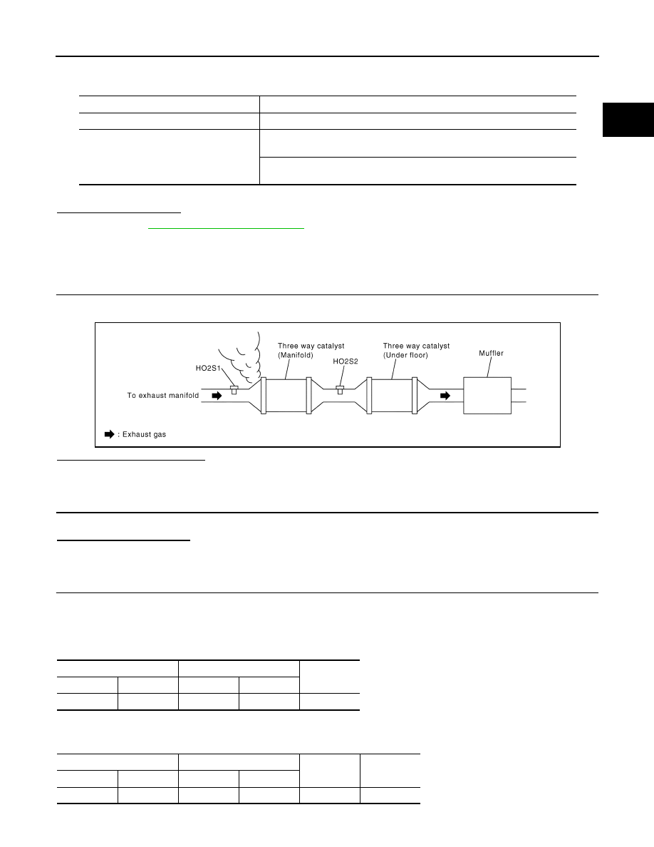
CHECK EXHAUST GAS LEAK
1.
Start engine and run it at idle.
2.
Listen for an exhaust gas leak before three way catalyst (manifold).
Is exhaust gas leak detected?
YES
>> Repair or replace.
NO
>> GO TO 2.
2.
CHECK FOR INTAKE AIR LEAK
Listen for an intake air leak after the mass air flow sensor.
Is intake air leak detected?
YES
>> Repair or replace.
NO
>> GO TO 3.
3.
CHECK HEATED OXYGEN SENSOR 1 INPUT SIGNAL CIRCUIT
1.
Turn ignition switch OFF.
2.
Disconnect corresponding heated oxygen sensor 1 harness connector.
3.
Disconnect ECM harness connector.
4.
Check the continuity between heated oxygen sensor 1 harness connector and ECM harness connector.
5.
Check the continuity between heated oxygen sensor 1 harness connector or ECM harness connector and
ground.
Engine speed
Engine speed in the freeze frame data
±
400 rpm
Vehicle speed
Vehicle speed in the freeze frame data
±
10 km/h (6 MPH)
Engine coolant temperature (T) condition
When the freeze frame data shows lower than 70
°
C (158
°
F),
T should be lower than 70
°
C (158
°
F).
When the freeze frame data shows higher than or equal to 70
°
C (158
°
F),
T should be higher than or equal to 70
°
C (158
°
F).
SEC502D
Heated oxygen sensor 1
ECM
Continuity
Connector
Terminal
Connector
Terminal
F30
4
F8
49
Existed
Heated oxygen sensor 1
ECM
Ground
Continuity
Connector
Terminal
Connector
Terminal
F30
4
F8
49
Ground
Not existed

EC-180
< COMPONENT DIAGNOSIS >
[HR16DE (WITH EURO-OBD)]
P0172 FUEL INJECTION SYSTEM FUNCTION
6.
Also check harness for short to power.
Is the inspection result normal?
YES
>> GO TO 4.
NO
>> Repair open circuit or short to ground or short to power in harness or connectors.
4.
CHECK FUEL PRESSURE
1.
Release fuel pressure to zero. Refer to
2.
Install fuel pressure gauge and check fuel pressure. Refer to
Is the inspection result normal?
YES
>> GO TO 6.
NO
>> GO TO 5.
5.
DETECT MALFUNCTIONING PART
Check fuel hoses and fuel tubes for clogging.
Is the inspection result normal?
YES
>> Replace “fuel filter and fuel pump assembly”.
NO
>> Repair or replace
6.
CHECK MASS AIR FLOW SENSOR
With CONSULT-III
1.
Install all removed parts.
2.
Check “MASS AIR FLOW” in “DATA MONITOR” mode with CONSULT-III.
With GST
1.
Install all removed parts.
2.
Check mass air flow sensor signal in “Service $01” with GST.
Is the measurement value within the specification?
YES
>> GO TO 7.
NO
>> Check connectors for rusted terminals or loose connections in the mass air flow sensor circuit or
grounds. Refer to
.
7.
CHECK FUNCTION OF FUEL INJECTOR
With CONSULT-III
1.
Start engine.
2.
Perform “POWER BALANCE” in “ACTIVE TEST” mode with CONSULT-III.
3.
Make sure that each circuit produces a momentary engine speed drop.
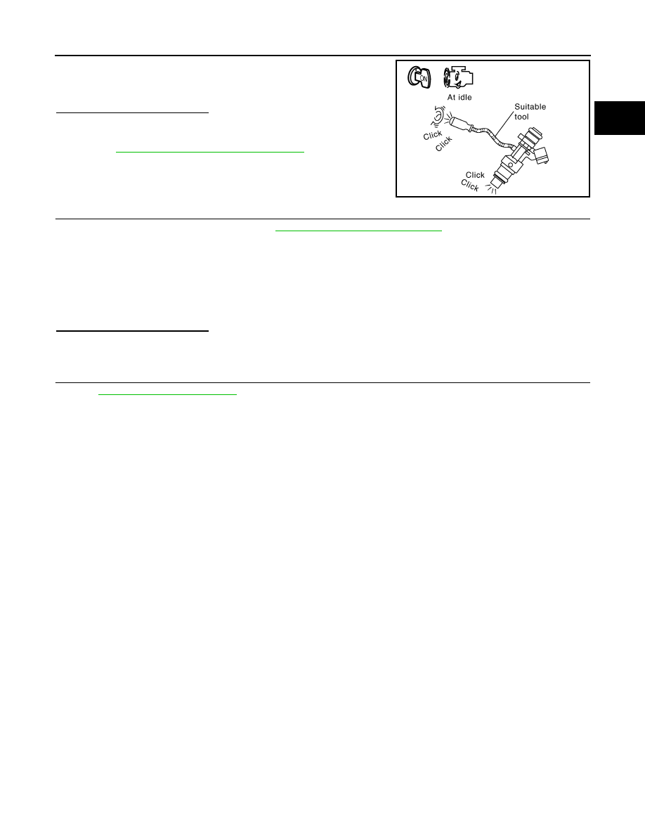
Without CONSULT-III
1.
Let engine idle.
At idling: Approximately 350 kPa (3.5 bar, 3.57 kg/cm
2
, 51 psi)
1.0 - 4.0 g·m/sec:
at idling
2.0 - 10.0 g·m/sec:
at 2,500 rpm
1.0 - 4.0 g·m/sec:
at idling
2.0 - 10.0 g·m/sec:
at 2,500 rpm
P0172 FUEL INJECTION SYSTEM FUNCTION
EC-181
< COMPONENT DIAGNOSIS >
[HR16DE (WITH EURO-OBD)]
C
D
E
F
G
H
I
J
K
L
M
A
EC
N
P
O
2.
Listen to each fuel injector operating sound.
Is the inspection result normal?
YES
>> GO TO 8.
NO
>> Perform trouble diagnosis for FUEL INJECTOR, refer to
EC-303, "Component Function Check"
8.
CHECK FUELINJECTOR
1.
Remove fuel injector assembly. Refer to
EM-35, "Removal and Installation"
.
Keep fuel hose and all fuel injectors connected to fuel tube.
2.
Confirm that the engine is cooled down and there are no fire hazards near the vehicle.
3.
Disconnect all fuel injector harness connectors.
4.
Disconnect all ignition coil harness connectors.
5.
Prepare pans or saucers under each fuel injectors.
6.
Crank engine for about 3 seconds.
Make sure fuel does not drip from fuel injector.
Is the inspection result normal?
YES
>> GO TO 9.
NO
>> Replace the fuel injectors from which fuel is dripping. Always replace O-ring with new one.
9.
CHECK INTERMITTENT INCIDENT
GI-39, "Intermittent Incident"
.
>> INSPECTION END
Clicking noise should be heard.
PBIB3332E
EC-182
< COMPONENT DIAGNOSIS >
[HR16DE (WITH EURO-OBD)]
P0222, P0223 TP SENSOR
P0222, P0223 TP SENSOR
Description
INFOID:0000000001056287
Electric throttle control actuator consists of throttle control motor,
throttle position sensor, etc. The throttle position sensor responds to
the throttle valve movement.
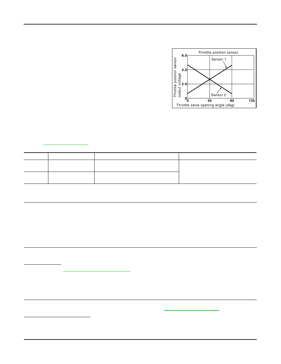
The throttle position sensor has two sensors. These sensors are a
kind of potentiometers which transform the throttle valve position into
output voltage, and emit the voltage signal to the ECM. In addition,
these sensors detect the opening and closing speed of the throttle
valve and feed the voltage signals to the ECM. The ECM judges the
current opening angle of the throttle valve from these signals and the
ECM controls the throttle control motor to make the throttle valve
opening angle properly in response to driving condition.
DTC Logic
INFOID:0000000001056288
DTC DETECTION LOGIC
NOTE:
If DTC P0222 or P0223 is displayed with DTC P1229, first perform the trouble diagnosis for DTC P1229.
Refer to
.
DTC CONFIRMATION PROCEDURE
1.
PRECONDITIONING
If DTC Confirmation Procedure has been previously conducted, always turn ignition switch OFF and wait at
least 10 seconds before conducting the next test.
TESTING CONDITION:
Before performing the following procedure, confirm that battery voltage is more than 10V at idle.
>> GO TO 2.
2.
PERFORM DTC CONFIRMATION PROCEDURE
1.
Start engine and let it idle for 1 second.
2.
Check DTC.
Is DTC detected?
YES
>> Go to
NO
>> INSPECTION END
Diagnosis Procedure
INFOID:0000000001056289
1.
CHECK GROUND CONNECTION
1.
Turn ignition switch OFF.
2.
Check ground connection E21. Refer to Ground Inspection in
.
Is the inspection result normal?
YES
>> GO TO 2.
NO
>> Repair or replace ground connection.
2.
CHECK THROTTLE POSITION SENSOR 1 POWER SUPPLY CIRCUIT
1.
Disconnect electric throttle control actuator harness connector.
2.
Turn ignition switch ON.
PBIB0145E
DTC No.
Trouble diagnosis name
DTC detecting condition
Possible cause
P0222
Throttle position sensor
1 circuit low input
An excessively low voltage from the TP sensor
1 is sent to ECM.
• Harness or connectors
(TP sensor 1 circuit is open or shorted.)
• Electric throttle control actuator
(TP sensor 1)
P0223
Throttle position sensor
1 circuit high input
An excessively high voltage from the TP sensor
1 is sent to ECM.
Нет комментариевНе стесняйтесь поделиться с нами вашим ценным мнением.
Текст