Nissan Qashqai (2007-2010). Manual — part 58
EM-180
< ON-VEHICLE REPAIR >
[MR20DE]
CAMSHAFT
Measure the diameter of valve lifter hole of cylinder head with an
inside micrometer (A).
VALVE LIFTER CLEARANCE
• (Valve lifter clearance) = (Valve lifter hole diameter) – (Valve lifter
outer diameter)
• If out of the standard, referring to the each standard of valve lifter
outer diameter and valve lifter hole diameter, replace either or both
valve lifter and cylinder head.
INSPECTION AFTER INSTALLATION
Inspection of Camshaft Sprocket (INT) Oil Groove
CAUTION:
• Perform this inspection only when DTC P0011 is detected in self-diagnostic results of CONSULT-III
and it is directed according to inspection procedure of EC section. Refer to
• Check when engine is cold so as to prevent burns by the splashing engine oil.
1.
Check engine oil level. Refer to
2.
Perform the following procedure so as to prevent the engine from being unintentionally started while
checking.
a.
Release the fuel pressure. Refer to
.
b.
Remove intake manifold. Refer to
c.
Disconnect ignition coil and injector harness connectors.
3.
Remove intake valve timing control solenoid valve. Refer to
.
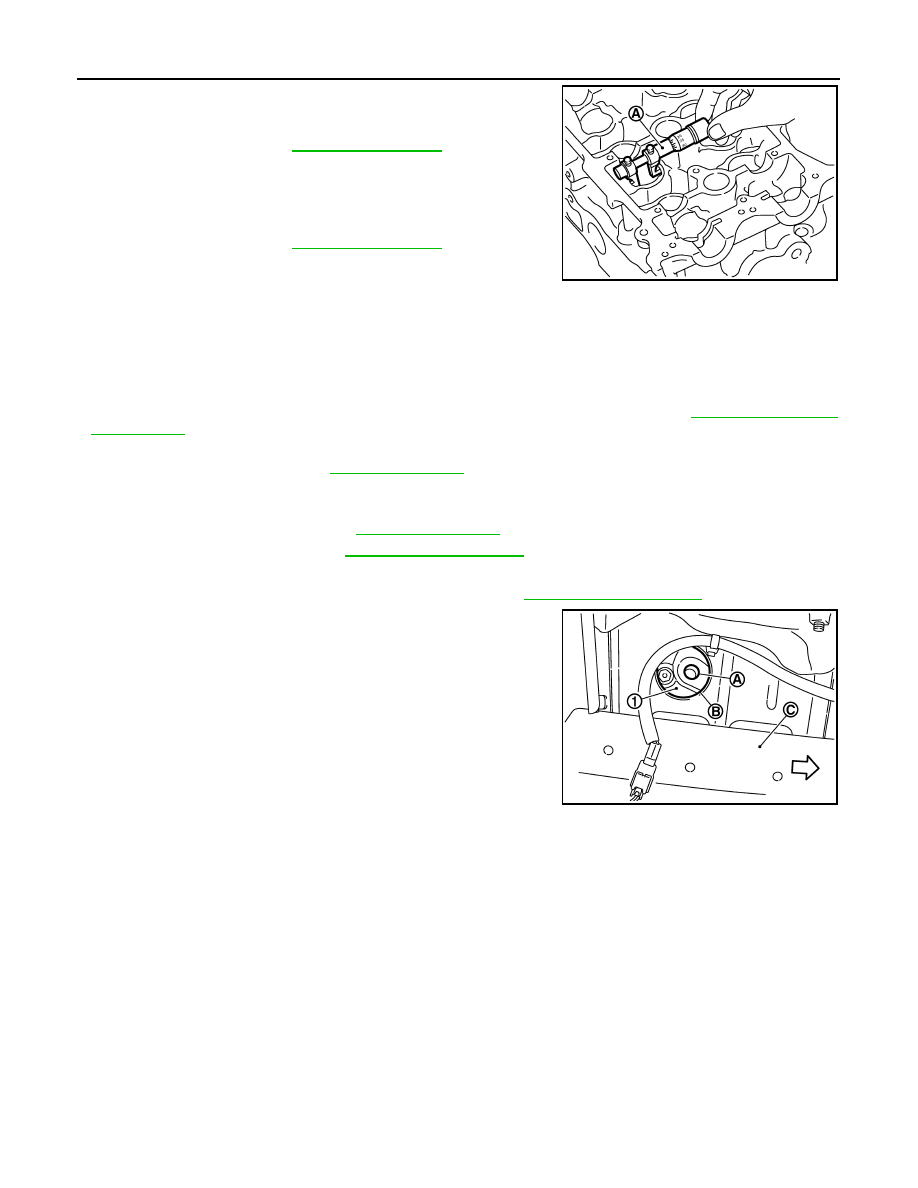
4.
Clean the mounting area of intake valve timing control solenoid
valve, and then insert a clean waste with no oil adhesion into the
oil hole (A) of the cylinder head.
5.
Install engine mounting insulator (RH). (After the removal of
intake valve timing control solenoid valve and insertion of a
waste into the oil hole.)
6.
Perform cranking to check that engine oil comes out from the oil hole (mounting hole of intake valve timing
control solenoid valve) of cylinder head.
• Regarding the engine oil check, judge it by the amount of oil adhered to the wasted inserted into the oil
hole.
WARNING:
• Never insert fingers into the oil hole from the service hole of the member on the RH side.
• Be careful not to touch rotating parts (drive belt, idler pulleys and crankshaft pulley, etc.).
CAUTION:
• Never perform cranking without installing the engine mounting insulator (RH).
• Prevent splashing by using a shop cloth so as to prevent the worker from injury from engine oil
and so as to prevent engine oil contamination.
• Prevent splashing by using a shop cloth so as to prevent engine oil from being splashed to
engine and vehicle. Especially, be careful not to apply engine oil to rubber parts of drive belt,
engine mounting insulator, etc. Wipe engine oil off immediately if it is splashed.
7.
Perform the following inspection if engine oil does not come out from intake valve timing control solenoid
valve oil hole of the cylinder head.
Standard
: Refer to
Standard
: Refer to
PBIC3184J
1
: Front cover
B
: Service hole
C
: Member on RH side
:Engine front
PBIC3191J

CAMSHAFT
EM-181
< ON-VEHICLE REPAIR >
[MR20DE]
C
D
E
F
G
H
I
J
K
L
M
A
EM
N
P
O
• Remove oil filter (for intake valve timing control solenoid), and then clean it. Refer to
.
• Clean oil groove between oil strainer and intake valve timing control solenoid valve. Refer to
LU-11, "Engine Lubrication System Schematic"
.
8.
Remove components between intake valve timing control solenoid valve and camshaft sprocket (INT),
and then check each oil groove for clogging.
• Clean oil groove if necessary. Refer to
LU-11, "Engine Lubrication System"
and
9.
After inspection, install removed parts in the reverse order.
EM-182
< ON-VEHICLE REPAIR >
[MR20DE]
OIL SEAL
OIL SEAL
VALVE OIL SEAL
VALVE OIL SEAL : Removal and Installation
INFOID:0000000000893953
REMOVAL
1.
Remove camshafts. Refer to
.
2.
Remove valve lifters. Refer to
.
3.
Rotate crankshaft, and set piston whose valve oil seal is to be removed to TDC. This will prevent valve
from dropping into cylinder.
CAUTION:
When rotating crankshaft, be careful to avoid scarring front cover with timing chain.
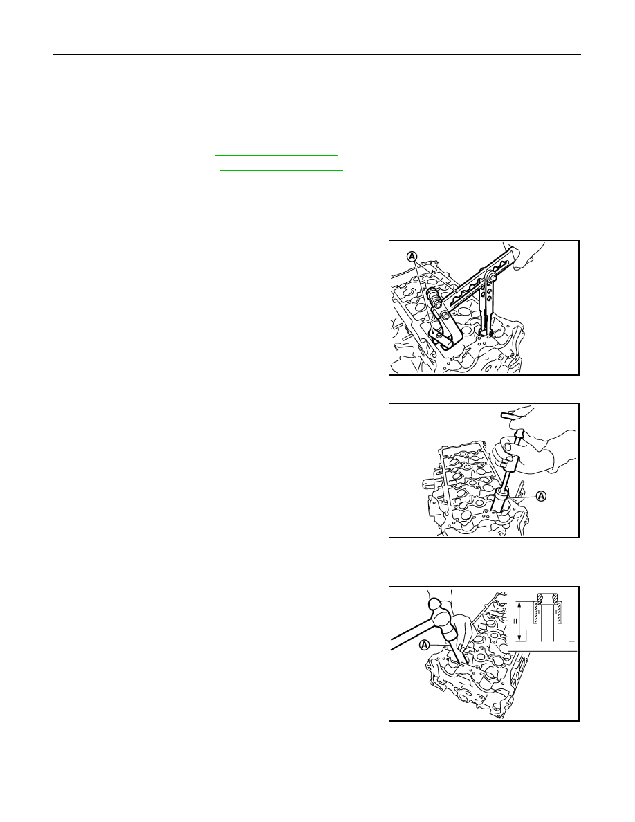
4.
Remove valve collet.
• Compress valve spring with the valve spring compressor, the
attachment and the adapter [SST: KV10116200] (A).
CAUTION:
Be careful not to damage valve lifter holes.
5.
Remove valve spring retainer, valve spring and valve spring seat.
6.
Remove valve oil seal with the valve oil seal puller [SST:
KV10107902] (A).
INSTALLATION
1.
Apply new engine oil to valve oil seal joint surface and seal lip.
2.
Press in valve oil seal to the height “H” shown in the figure with
the valve oil seal drift [SST: KV10115600] (A).
3.
Install in the reverse order of removal, for the rest of parts.
FRONT OIL SEAL
FRONT OIL SEAL : Removal and Installation
INFOID:0000000000893954
PBIC3209J
PBIC3210J
Height “H”
: 15.1 - 15.7 mm (0.594 - 0.618 in)
PBIC3211J
OIL SEAL
EM-183
< ON-VEHICLE REPAIR >
[MR20DE]
C
D
E
F
G
H
I
J
K
L
M
A
EM
N
P
O
REMOVAL
1.
Remove the following parts.
• Front fender protector (RH): Refer to
• Drive belt: Refer to
.
• Crankshaft pulley: Refer to
.
2.
Remove front oil seal with a suitable tool.
CAUTION:
Be careful not to damage front cover and crankshaft.
INSTALLATION
1.
Apply new engine oil to new front oil seal joint surface and seal lip.
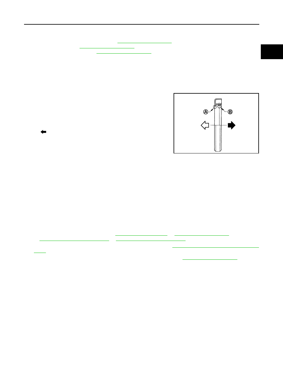
2.
Install front oil seal so that each seal lip is oriented as shown in
the figure.
• Press-fit front oil seal using a suitable drift with outer diameter
57 mm (2.24 in) and inner diameter 45 mm (1.77 in).
CAUTION:
• Be careful not to damage front cover and crankshaft.
• Press-fit oil seal straight to avoid causing burrs or tilting.
3.
Install in the reverse order of removal, for the rest of parts.
REAR OIL SEAL
REAR OIL SEAL : Removal and Installation
INFOID:0000000000893955
REMOVAL
1.
Remove transaxle assembly. Refer to
or
(M/T models)
(CVT models).
2.
Remove clutch cover and clutch disk (M/T models). Refer to
CL-16, "HR16DE, MR20DE : Exploded
.
3.
Remove drive plate (CVT models) or flywheel (M/T models). Refer to
4.
Remove rear oil seal with a suitable tool.
CAUTION:
Be careful not to damage crankshaft and cylinder block.
INSTALLATION
1.
Apply the liquid gasket lightly to entire outside area of new rear oil seal.
Use Genuine Liquid Gasket or equivalent.
A
: Dust seal lip
B
: Oil seal lip
: Engine outside
: Engine inside
Within 0.3 mm (0.012 in) toward engine front (crankshaft pulley side)
Within 0.5 mm (0.020 in) toward engine rear (crankshaft sprocket side)
PBIC3485J
Нет комментариевНе стесняйтесь поделиться с нами вашим ценным мнением.
Текст