Nissan Qashqai (2007-2010). Manual — part 448

ON BOARD DIAGNOSTIC (OBD) SYSTEM
EC-1311
< FUNCTION DIAGNOSIS >
[K9K]
C
D
E
F
G
H
I
J
K
L
M
A
EC
N
P
O
ON BOARD DIAGNOSTIC (OBD) SYSTEM
Diagnosis Description
INFOID:0000000000902323
The ECM controls the display on the instrument panel of certain information relating to the operation of the
engine.
Four functions are involved here: The OBD malfunction indicator [MI (Yellow)] for the EOBD (European On
Board Diagnostics), the pre/post heating, the engine coolant temperature and engine malfunction [MI (Red)].
These four functions are represented by four lights given out by the ECM
GLOW LAMP
This lamp indicates that the glow control system has been activated.
ENGINE COOLANT TEMPERATURE LIGHT
This light is used as an indicator of engine overheating.
• In the event of overheating, it is up to the driver whether to stop the vehicle or not.
MALFUNCTION INDICATOR
The OBD malfunction indicator [MI (Yellow)] is used to alert the driver to the existence of engine control sys-
tem malfunctions involving excessive pollution or if the EOBD system is deactivated.
The ECM makes a request for lighting of the MI (Yellow) only where there is a malfunction present at the end
of three consecutive cycles.
The 3-second visual check upon powering up (automatic test procedure controlled by the IPDM E/R) is per-
formed by the ECM.
In the event of a confirmed OBD malfunction by lighting of the MI, no flashing of the light must be observed fol-
lowing the lighting test.
DTCs Causing MI to Light
ENGINE WARNING LIGHT
In the event of an engine malfunction, the ECM may request the display of an engine warning light [MI (Red)].
HOW TO ERASE DTC, 1ST TRIP DTC AND 2ND TRIP DTC
With CONSULT-III
The emission related diagnostic information in the ECM can be erased by selecting “ALL ERASE” in the
“Description” of “FINAL CHECK” mode with CONSULT-III.
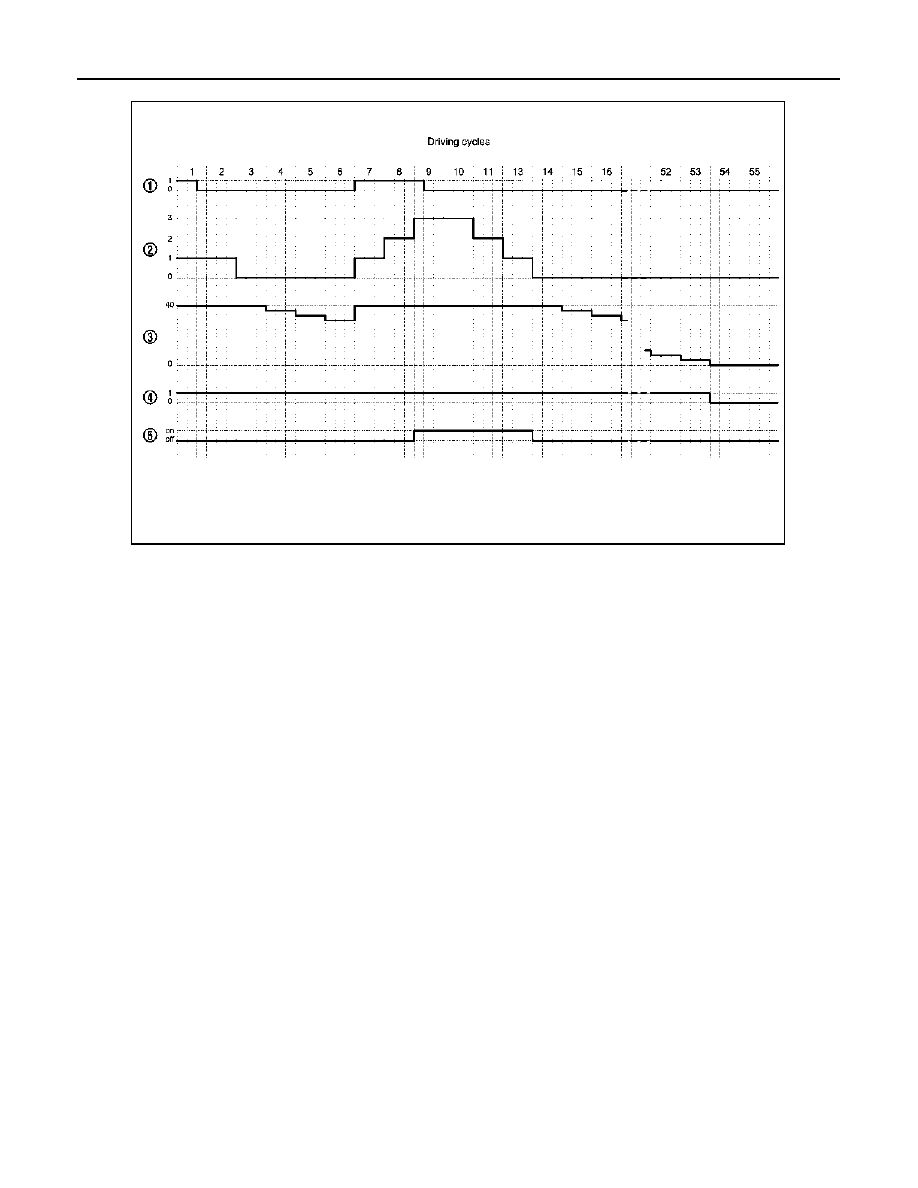
MI OPERATION CHART
Some malfunction must switch on MI to warn driver, that his engine emissions exceed OBD thresholds (Euro 3
x 2.5).
The rule is to switch on MI after 3 consecutive driving cycles (engine start + engine stop + power latch) with a
present OBD malfunction.
To switch off the MI (without CONSULT-III), vehicle has to drive 3 consecutive cycles without present OBD
malfunction.
Ignition switch OFF
→
ON transition, MI remains switched on in pre-drive check mode until engine start.If MI
does not switch off whereas engine is running, there is at least one present OBD malfunction.
DTC
Description
Reference page
P0201
Cylinder 1 fuel injector control circuit
P0202
Cylinder 2 fuel injector control circuit
P0203
Cylinder 3 fuel injector control circuit
P0204
Cylinder 4 fuel injector control circuit
P0409
EGR Volume control valve control position sensor circuit
P0606
ECM
P2413
EGR volume control valve
EC-1312
< FUNCTION DIAGNOSIS >
[K9K]
ON BOARD DIAGNOSTIC (OBD) SYSTEM
1.
Present malfunction
2.
Driving cycle counter
3.
Warm up cycle counter
4.
Memorised malfunction
5.
MI state
NOTE: Driving cycle and warm up cycle are both detected in the same cycle.
JMBIA0431GB

POWER SUPPLY AND GROUND CIRCUIT
EC-1313
< COMPONENT DIAGNOSIS >
[K9K]
C
D
E
F
G
H
I
J
K
L
M
A
EC
N
P
O
COMPONENT DIAGNOSIS
POWER SUPPLY AND GROUND CIRCUIT
Diagnosis Procedure
INFOID:0000000001070365
1.
INSPECTION START
Start engine.
Is engine running?
YES
>> GO TO 6.
NO
>> GO TO 2.
2.
CHECK ECM POWER SUPPLY CIRCUIT-I
1.
Turn ignition switch OFF and then ON.
2.
Check the voltage between ECM harness connector and ground.
Is the inspection result normal?
YES
>> GO TO 4.
NO
>> GO TO 3.
3.
DETECT MALFUNCTIONING PART
Check the following.
• 10A fuse (No. 5)
• Harness for open or short between ECM and fuse
>> Repair open circuit or short to ground or short to power in harness or connectors.
4.
CHECK GROUND CONNECTION-I
1.
Turn ignition switch OFF.
2.
Check ground connection E17. Refer to Ground Inspection in
.
Is the inspection result normal?
YES
>> GO TO 5.
NO
>> Repair or replace ground connection.
5.
CHECK ECM GROUND CIRCUIT FOR OPEN AND SHORT-I
1.
Disconnect ECM harness connectors.
2.
Check the continuity between ECM harness connector and ground.
3.
Also check harness for short to power.
Is the inspection result normal?
YES
>> GO TO 6.
NO
>> Repair open circuit or short to power in harness or connectors.
6.
CHECK ECM POWER SUPPLY CIRCUIT-III
1.
Turn ignition switch OFF and wait at least 10 seconds.
ECM
Ground
Voltage
Connector
Terminal
F68
69
Ground
Battery voltage
ECM
Ground
Continuity
Connector
Terminal
E60
123
Ground
Existed
124
125
128

EC-1314
< COMPONENT DIAGNOSIS >
[K9K]
POWER SUPPLY AND GROUND CIRCUIT
2.
Check the voltage between ECM harness connector and ground.
Is the inspection result normal?
YES
>> GO TO 12.
NO-1
>> Battery voltage does not exist: GO TO 7.
NO-2
>> Battery voltage exists for more than a few seconds: GO TO 10.
7.
CHECK ECM POWER SUPPLY CIRCUIT-IV
1.
Turn ignition switch OFF and wait at least 10 seconds.
2.
Check the voltage between ECM harness connector and ground.
Is the inspection result normal?
YES
>> GO TO 8.
NO
>> GO TO 10.
8.
CHECK ECM POWER SUPPLY CIRCUIT-V
1.
Disconnect ECM harness connector.
2.
Disconnect IPDM E/R harness connector E11.
3.
Check the continuity between ECM harness connector and IPDM E/R harness connector.
4.
Also check harness for short to ground and short to power.
Is the inspection result normal?
YES
>> GO TO 14.
NO
>> GO TO 9.
9.
DETECT MALFUNCTIONING PART
Check the following.
• Harness or connectors E7, E121
• Harness for open or short between ECM and IPDM E/R
>> Repair open circuit or short to ground or short to power in harness or connectors.
10.
CHECK ECM POWER SUPPLY CIRCUIT-VI
1.
Disconnect ECM harness connector.
2.
Disconnect IPDM E/R harness connector E11.
3.
Check the continuity between ECM harness connector and IPDM E/R harness connector.
4.
Also check harness for short to ground and short to power.
ECM
Ground
Voltage
Connector
Terminal
F68
53
Ground
After turning ignition switch OFF, battery volt-
age will exist for a few seconds, then drop ap-
proximately 0V.
54
ECM
Ground
Voltage
Connector
Terminal
F68
60
Ground
Battery voltage
ECM
IPDM E/R
Continuity
Connector
Terminal
Connector
Terminal
E68
53
E11
9
Existed
54
ECM
IPDM E/R
Continuity
Connector
Terminal
Connector
Terminal
F68
60
E11
15
Existed
Нет комментариевНе стесняйтесь поделиться с нами вашим ценным мнением.
Текст