Nissan Qashqai (2007-2010). Manual — part 254

P1805 BRAKE SWITCH
EC-535
< COMPONENT DIAGNOSIS >
[HR16DE (WITHOUT EURO-OBD)]
C
D
E
F
G
H
I
J
K
L
M
A
EC
N
P
O
P1805 BRAKE SWITCH
Description
INFOID:0000000001096931
Brake switch signal is applied to the ECM through the stop lamp switch when the brake pedal is depressed.
This signal is used mainly to decrease the engine speed when the vehicle is driving.
DTC Logic
INFOID:0000000001096932
DTC DETECTION LOGIC
DTC CONFIRMATION PROCEDURE
1.
PERFORM DTC CONFIRMATION PROCEDURE
1.
Turn ignition switch ON.
2.
Fully depress the brake pedal for at least 5 seconds.
3.
Erase the DTC with CONSULT-III.
4.
Check 1st trip DTC.
Is 1st trip DTC detected?
YES
>> Go to
NO
>> INSPECTION END
Diagnosis Procedure
INFOID:0000000001096933
1.
CHECK STOP LAMP SWITCH CIRCUIT
1.
Turn ignition switch OFF.
2.
Check the stop lamp when depressing and releasing the brake pedal.
Is 1st trip DTC detected?
YES
>> GO TO 4.
NO
>> GO TO 2.
2.
CHECK STOP LAMP SWITCH POWER SUPPLY CIRCUIT
1.
Turn ignition switch OFF.
2.
Disconnect stop lamp switch harness connector.
3.
Check the voltage between stop lamp switch harness connector and ground.
Is the inspection result normal?
YES
>> GO TO 4.
NO
>> GO TO 3.
3.
DETECT MALFUNCTIONING PART
Check the following.
• Harness connectors E105, M77
DTC No.
Trouble diagnosis name
DTC detecting condition
Possible cause
P1805
Brake switch
A brake switch signal is not sent to ECM for ex-
tremely long time while the vehicle is driving.
• Harness or connectors
(Stop lamp switch circuit is open or short-
ed.)
• Stop lamp switch
Brake pedal
Stop lamp
Fully released
Not illuminated
Slightly depressed
Illuminated
Stop lamp switch
Ground
Voltage
Connector
Terminal
E114
1
Ground
Battery voltage

EC-536
< COMPONENT DIAGNOSIS >
[HR16DE (WITHOUT EURO-OBD)]
P1805 BRAKE SWITCH
• 10A fuse (No. 11)
• Harness for open or short between stop lamp switch and battery
>> Repair open circuit or short to ground or short to power in harness or connectors.
4.
CHECK STOP LAMP SWITCH INPUT SIGNAL CIRCUIT FOR OPEN AND SHORT
1.
Disconnect ECM harness connector.
2.
Check the continuity between ECM harness connector and stop lamp switch harness connector.
3.
Also check harness for short to ground and short to power.
Is the inspection result normal?
YES
>> GO TO 5.
NG
>> Repair open circuit or short to ground or short to power in harness or connectors.
5.
CHECK STOP LAMP SWITCH
EC-537, "Component Inspection (Stop Lamp Switch)"
.
Is the inspection result normal?
YES
>> GO TO 6.
NO
>> Replace stop lamp switch.
6.
CHECK INTERMITTENT INCIDENT
GI-39, "Intermittent Incident"
>> INSPECTION END
Component Inspection (Stop Lamp Switch)
INFOID:0000000001096934
1.
CHECK STOP LAMP SWITCH-I
1.
Turn ignition switch OFF.
2.
Disconnect stop lamp switch harness connector.
3.
Check the continuity between stop lamp switch terminals under the following conditions.
Is the inspection result normal?
YES
>> INSPECTION END
NO
>> GO TO 2.
2.
CHECK STOP LAMP SWITCH-II
1.
Adjust stop lamp switch installation. Refer to
BR-18, "Inspection and Adjustment"
(LHD) or
(LHD).
2.
Check the continuity between stop lamp switch terminals under the following conditions.
Is the inspection result normal?
YES
>> INSPECTION END
NO
>> Replace stop lamp switch.
ECM
Stop lamp switch
Continuity
Connector
Terminal
Connector
Terminal
E16
99
E114
2
Existed
Terminals
Condition
Continuity
1 and 2
Brake pedal
Fully released
Not existed
Slightly depressed
Existed
Terminals
Condition
Continuity
1 and 2
Brake pedal
Fully released
Not existed
Slightly depressed
Existed
P2122, P2123 APP SENSOR
EC-537
< COMPONENT DIAGNOSIS >
[HR16DE (WITHOUT EURO-OBD)]
C
D
E
F
G
H
I
J
K
L
M
A
EC
N
P
O
P2122, P2123 APP SENSOR
Description
INFOID:0000000001096935
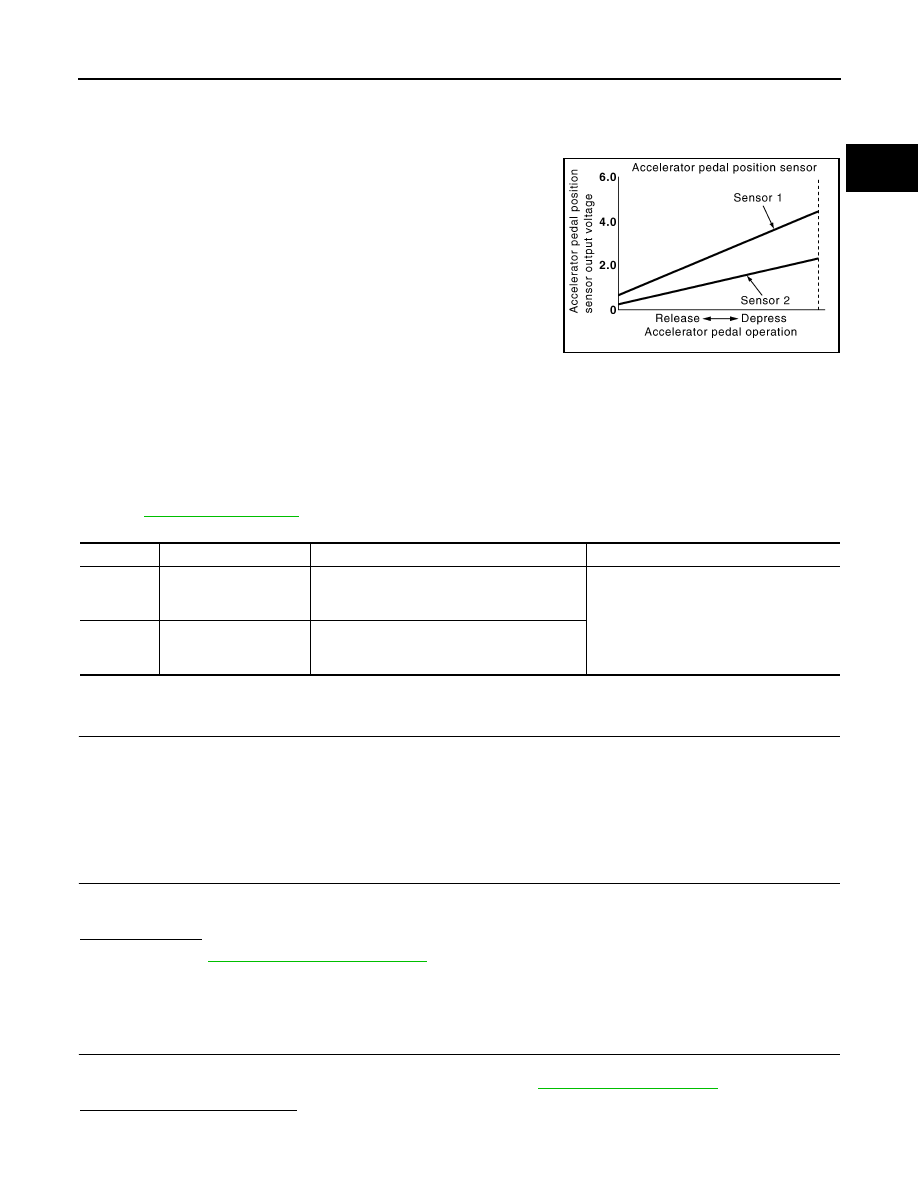
The accelerator pedal position sensor is installed on the upper end
of the accelerator pedal assembly. The sensor detects the accelera-
tor position and sends a signal to the ECM.
Accelerator pedal position sensor has two sensors. These sensors
are a kind of potentiometers which transform the accelerator pedal
position into output voltage, and emit the voltage signal to the ECM.
In addition, these sensors detect the opening and closing speed of
the accelerator pedal and feed the voltage signals to the ECM. The
ECM judges the current opening angle of the accelerator pedal from
these signals and controls the throttle control motor based on these
signals.
Idle position of the accelerator pedal is determined by the ECM
receiving the signal from the accelerator pedal position sensor. The ECM uses this signal for the engine oper-
ation such as fuel cut.
DTC Logic
INFOID:0000000001096936
DTC DETECTION LOGIC
NOTE:
If DTC P2122 or P2123 is displayed with DTC P1229, first perform the trouble diagnosis for DTC P1229.
Refer to
.
DTC CONFIRMATION PROCEDURE
1.
PRECONDITIONING
If DTC Confirmation Procedure has been previously conducted, always turn ignition switch OFF and wait at
least 10 seconds before conducting the next test.
TESTING CONDITION:
Before performing the following procedure, confirm that battery voltage is more than 10V at idle.
>> GO TO 2.
2.
PERFORM DTC CONFIRMATION PROCEDURE
1.
Start engine and let it idle for 1 second.
2.
Check DTC.
Is DTC detected?
YES
>> Go to
NO
>> INSPECTION END
Diagnosis Procedure
INFOID:0000000001096937
1.
CHECK GROUND CONNECTION
1.
Turn ignition switch OFF.
2.
Check ground connection E21. Refer to Ground Inspection in
.
Is the inspection result normal?
YES
>> GO TO 2.
PBIB1741E
DTC No.
Trouble diagnosis name
DTC detecting condition
Possible cause
P2122
Accelerator pedal posi-
tion sensor 1 circuit low
input
An excessively low voltage from the APP sen-
sor 1 is sent to ECM.
• Harness or connectors
(APP sensor 1 circuit is open or shorted.)
• Accelerator pedal position sensor
(APP sensor 1)
P2123
Accelerator pedal posi-
tion sensor 1 circuit high
input
An excessively high voltage from the APP sen-
sor 1 is sent to ECM.

EC-538
< COMPONENT DIAGNOSIS >
[HR16DE (WITHOUT EURO-OBD)]
P2122, P2123 APP SENSOR
NO
>> Repair or replace ground connection.
2.
CHECK APP SENSOR 1 POWER SUPPLY CIRCUIT
1.
Disconnect accelerator pedal position (APP) sensor harness connector.
2.
Turn ignition switch ON.
3.
Check the voltage between APP sensor harness connector and ground.
Is the inspection result normal?
YES
>> GO TO 3.
NO
>> Repair open circuit or short to ground or short to power in harness or connectors.
3.
CHECK APP SENSOR 1 GROUND CIRCUIT FOR OPEN AND SHORT
1.
Turn ignition switch OFF.
2.
Disconnect ECM harness connector.
3.
Check the continuity between APP sensor harness connector and ECM harness connector.
4.
Also check harness for short to ground and short to power.
Is the inspection result normal?
YES
>> GO TO 4.
NO
>> Repair open circuit or short to ground or short to power in harness or connectors.
4.
CHECK APP SENSOR 1 INPUT SIGNAL CIRCUIT FOR OPEN AND SHORT
1.
Check the continuity between APP sensor harness connector and ECM harness connector.
2.
Also check harness for short to ground and short to power.
Is the inspection result normal?
YES
>> GO TO 5.
NO
>> Repair open circuit or short to ground or short to power in harness or connectors.
5.
CHECK APP SENSOR
EC-541, "Component Inspection"
Is the inspection result normal?
YES
>> GO TO 7.
NO
>> GO TO 6.
6.
REPLACE ACCELERATOR PEDAL ASSEMBLY
1.
Replace accelerator pedal assembly.
2.
Go to
EC-541, "Special Repair Requirement"
.
>> INSPECTION END
7.
CHECK INTERMITTENT INCIDENT
GI-39, "Intermittent Incident"
>> INSPECTION END
APP sensor
Ground
Voltage
Connector
Terminal
E110
4
Ground
Approx. 5V
APP sensor
ECM
Continuity
Connector
Terminal
Connector
Terminal
E110
2
E16
111
Existed
APP sensor
ECM
Continuity
Connector
Terminal
Connector
Terminal
E110
3
E16
110
Existed
Нет комментариевНе стесняйтесь поделиться с нами вашим ценным мнением.
Текст