Nissan Qashqai (2007-2010). Manual — part 694
BRAKE BOOSTER
BR-75
< ON-VEHICLE REPAIR >
[RHD]
C
D
E
G
H
I
J
K
L
M
A
B
BR
N
O
P
• Be careful not to damage brake booster stud bolt threads. If brake booster is tilted during installa-
tion, the dash panel may damage the threads.
• Never deform or bend the brake tubes when installing the brake booster.
• Always use a new gasket between the brake booster and the spacer.
• Replace the clevis pin if it is damaged. Refer to
BR-62, "Inspection and Adjustment"
• After installation, perform the air bleeding. Refer to
BR-56, "Bleeding Brake System"
.
CAUTION:
Never reuse drained brake fluid.
Inspection and Adjustment
INFOID:0000000000938076
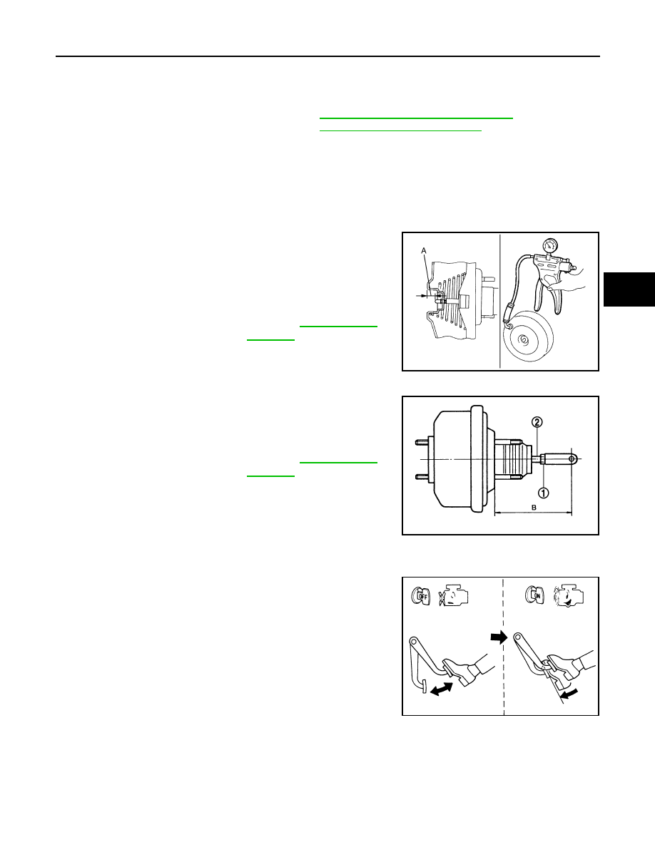
INSPECTION AFTER REMOVAL
Output Rod Length Inspection
1.
With a handy vacuum pomp, apply vacuum pressure of
−
66.7
kPa (
−
500 mmHg,
−
19.70 inHg,
−
0.667 bar) to the brake
booster.
2.
Check the output rod length (A).
Input Rod Length Inspection
1.
Loosen the lock nut (1) and adjust the input rod (2) to the speci-
fied length (B).
2.
Tighten the lock nut to the specified torque.
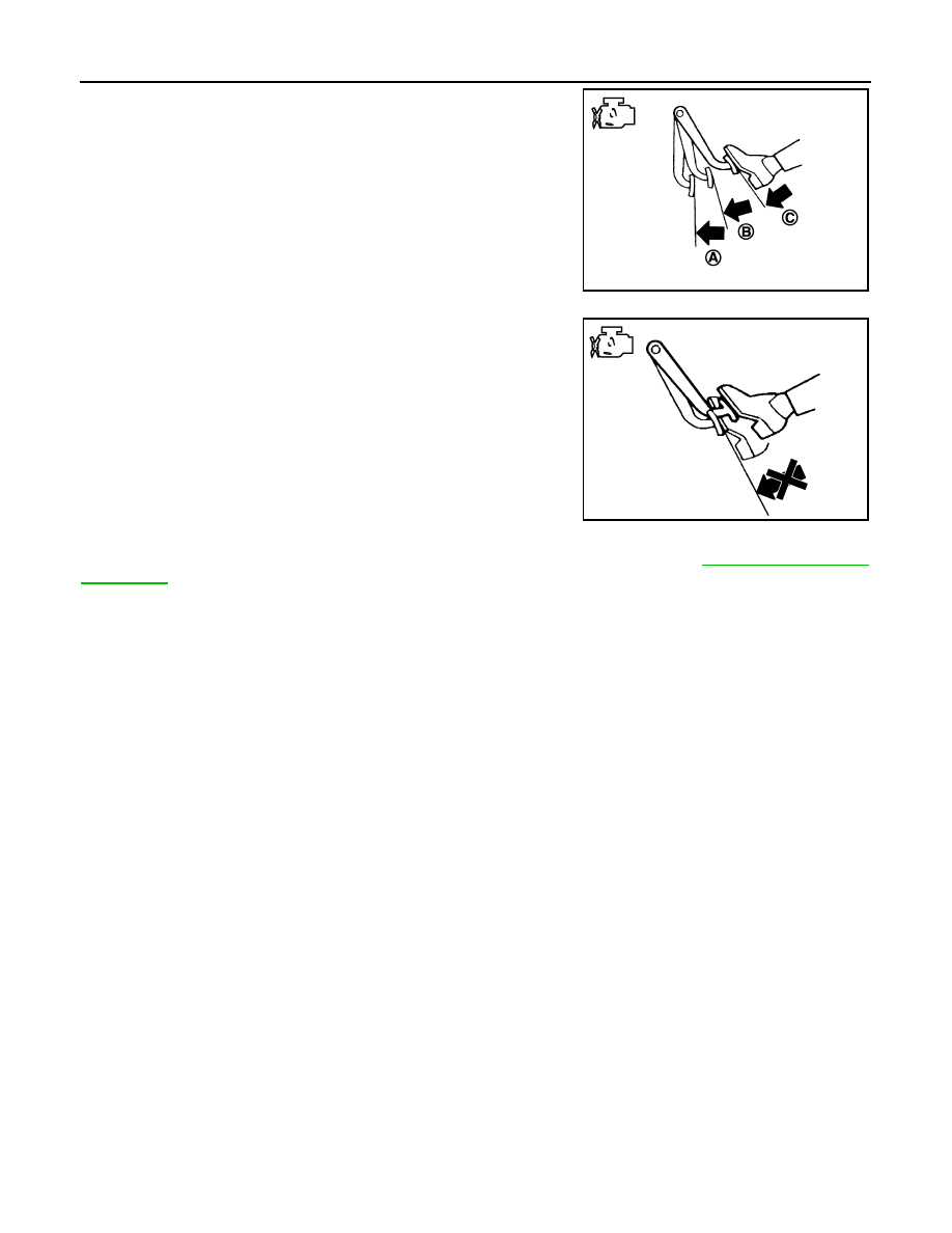
INSPECTION AFTER INSTALLATION
Operation
Depress the brake pedal several times at 5-second intervals with the
engine stopped. Start the engine with the brake pedal fully
depressed. Check that the clearance between brake pedal and dash
lower pane decreases.
NOTE:
A slight impact with a small click may be felt on the pedal when the
brake pedal is fully depressed. This is a normal phenomenon due to
the brake system operation.
Air Tight
Standard
Output rod length (A)
: Refer to
.
JPFIA0021ZZ
Standard
Input rod length (B)
: Refer to
.
JPFIA0020ZZ
BRA0037D
BR-76
< ON-VEHICLE REPAIR >
[RHD]
BRAKE BOOSTER
• Idle the engine for 1 minute to apply vacuum to the brake booster,
and stop the engine. Then depress the brake pedal several times
at 5-second intervals until the accumulated vacuum is released to
atmospheric pressure. Check that the clearance between brake
pedal and dash lower panel gradually increases (A
→
B
→
C) each
time the brake pedal is depressed during this operation.
• Depress the brake pedal with the engine running. Then stop the
engine while holding down the brake pedal. Check that the brake
pedal stroke does not change after holding down the brake pedal
for 30 seconds or more.
NOTE:
A slight impact with a small click may be felt on the pedal when the
brake pedal is fully depressed. This is a normal phenomenon due
to the brake system operation.
ADJUSTMENT AFTER INSTALLTION
Perform the brake pedal adjustment after installing the brake pedal assembly. Refer to
.
JPFIA0043ZZ
JPFIA0044ZZ
VACUUM LINES
BR-77
< ON-VEHICLE REPAIR >
[RHD]
C
D
E
G
H
I
J
K
L
M
A
B
BR
N
O
P
VACUUM LINES
HR16DE/MR20DE MODELS
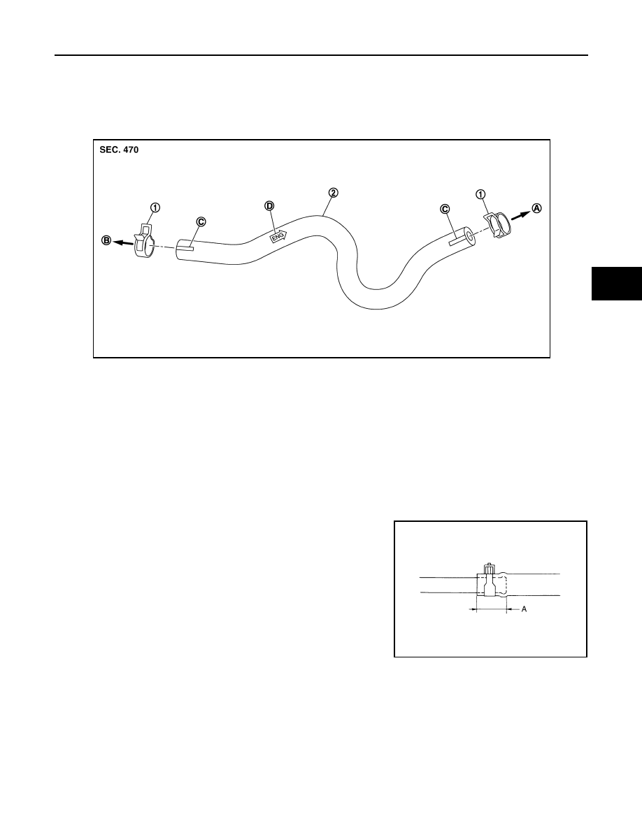
HR16DE/MR20DE MODELS : Exploded View
INFOID:0000000000938077
HR16DE/MR20DE MODELS : Removal and Installation
INFOID:0000000000938078
REMOVAL
Remove the vacuum hose.
INSTALLATION
Install the vacuum hose.
CAUTION:
• Because vacuum hose contains a check valve, it must be
installed in the correct position. Refer to the stamp to confirm
correct installation. Brake booster will not operate normally if
the hose is installed in the wrong direction.
• Insert vacuum hose at least 24 mm (0.94 in) (A).
• Never use lubricating oil during assembly.
• Face the marking side up when assembling of vacuum hose.
HR16DE/MR20DE MODELS : Inspection
INFOID:0000000000938079
INSPECTION AFTER REMOVAL
Appearance
Check for correct assembly, damage and deterioration.
Check Valve Airtightness
1.
Clamp
2.
Vacuum hose (built in check valve)
A.
To intake manifold
B.
To brake booster
C.
Paint mark
D.
Stamp indicating engine direction
JPFIA0087ZZ
JPFIA0023ZZ
BR-78
< ON-VEHICLE REPAIR >
[RHD]
VACUUM LINES
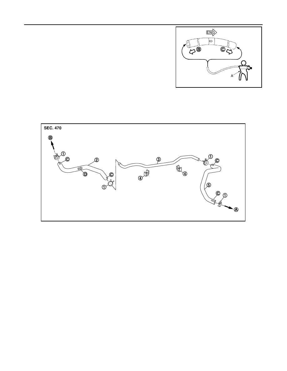
• Use a handy vacuum pump (A) to check.
• Replace vacuum hose assembly if vacuum hose and check valve
are malfunctioning.
K9K MODELS
K9K MODELS : Exploded View
INFOID:0000000000938080
K9K MODELS : Removal and Installation
INFOID:0000000000938081
REMOVAL
Remove the vacuum hose and tube.
INSTALLATION
Install the vacuum hose and tube.
CAUTION:
When connected to the brake booster side (B):
Vacuum should decrease within 1.3 kPa (10 mm-
Hg, 0.39 inHg, 0.013 bar) for 15 seconds under a
vacuum of
−
66.7 kPa (
−
500 mmHg,
−
19.70 inHg,
−
0.667 bar).
When connected to the engine side (C):
Vacuum should not exist.
JPFIA0024ZZ
1.
Clamp
2.
Vacuum hose (built in check valve)
3.
vacuum tube
4.
Clip
5.
Vacuum hose
A.
To vacuum pomp
B.
To brake booster
C.
Paint mark
D.
Stamp indicating engine direction
JPFIA0088ZZ
Нет комментариевНе стесняйтесь поделиться с нами вашим ценным мнением.
Текст