Nissan Qashqai (2007-2010). Manual — part 270
ECM
EC-599
< ECU DIAGNOSIS >
[HR16DE (WITHOUT EURO-OBD)]
C
D
E
F
G
H
I
J
K
L
M
A
EC
N
P
O
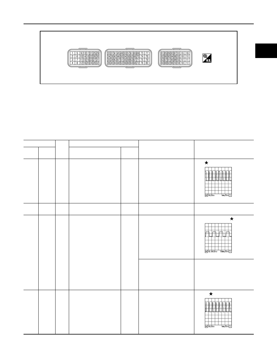
TERMINAL LAYOUT
PHYSICAL VALUES
NOTE:
• ECM is located in the engine room left side near battery.
• Specification data are reference values and are measured between each terminal and ground.
• Pulse signal is measured by CONSULT-III.
CAUTION:
Do not use ECM ground terminals when measuring input/output voltage. Doing so may result in dam-
age to the ECMs transistor. Use a ground other than ECM terminals, such as the ground.
PBIA9221J
Terminal No.
Wire
color
Description
Condition
Value
(Approx.)
+
-–
Signal name
Input/
Output
1
Ground
L/W
Throttle control motor
(Open)
Output
[Ignition switch: ON]
• Engine stopped
• Shift lever: 1st
• Accelerator pedal: Fully de-
pressed
3.2V
2
Ground
R/Y
Throttle control motor relay
power supply
Input
[Ignition switch: ON]
BATTERY VOLTAGE
(11 - 14V)
3
Ground
LG/R
Heated oxygen sensor 1
heater
Output
[Engine is running]
• Warm up condition
• Engine speed: Below 3,600
rpm
Approximately 3.2V
[Engine is running]
• Warm-up condition
• Idle speed
[Engine is running]
• Engine speed: Above 3,600
rpm
BATTERY VOLTAGE (11 - 14V)
4
Ground
P
Throttle control motor
(Close)
Output
[Ignition switch: ON]
• Engine stopped
• Shift lever: 1st
• Accelerator pedal: Fully re-
leased
0 - 14V
PBIA8150J
PBIA8148J
PBIA8149J

EC-600
< ECU DIAGNOSIS >
[HR16DE (WITHOUT EURO-OBD)]
ECM
5
Ground
R
Heated oxygen sensor 2
heater
Output
[Engine is running]
• Engine speed: Below 3,900
rpm after the following con-
ditions are met
- Engine: after warming up
- Keeping the engine speed
between 3,500 and 4,000
rpm for 1 minute and at idle
for 1 minute under no load
10V
[Ignition switch: ON]
• Engine stopped
[Engine is running]
• Engine speed: Above 3,900
rpm
BATTERY VOLTAGE
(11 - 14V)
9
Ground
W/B
EVAP canister purge volume
control solenoid valve
Output
[Engine is running]
• Idle speed
BATTERY VOLTAGE
(11 - 14V)
[Engine is running]
• Engine speed: About 2,000
rpm (More than 100 sec-
onds after starting engine.)
BATTERY VOLTAGE
(11 - 14V)
10
11
Ground
B
B/W
ECM ground
—
[Engine is running]
• Idle speed
Body ground
15
Ground
G/L
Throttle control motor relay
Output
[Ignition switch: OFF]
BATTERY VOLTAGE
(11 - 14V)
[Ignition switch: ON]
0 - 1.0V
17
18
21
22
Ground
L/Y
BR/Y
R/G
SB
Ignition signal No. 1
Ignition signal No. 2
Ignition signal No. 4
Ignition signal No. 3
Output
[Engine is running]
• Warm-up condition
• Idle speed
NOTE:
The pulse cycle changes de-
pending on rpm at idle
0 - 0.3V
[Engine is running]
• Warm-up condition
• Engine speed: 2,500 rpm
0.2 - 0.5V
Terminal No.
Wire
color
Description
Condition
Value
(Approx.)
+
-–
Signal name
Input/
Output
PBIA8148J
PBIB0050E
PBIB0520E
PBIA9265J
PBIA9266J

ECM
EC-601
< ECU DIAGNOSIS >
[HR16DE (WITHOUT EURO-OBD)]
C
D
E
F
G
H
I
J
K
L
M
A
EC
N
P
O
23
Ground
B/O
Fuel pump relay
Output
[Ignition switch: ON]
• For 1 second after turning
ignition switch ON
[Engine is running]
0 - 1.0V
[Ignition switch: ON]
• More than a few seconds af-
ter turning ignition switch
ON
BATTERY VOLTAGE
(11 - 14V)
25
29
30
31
Ground
R/O
Y
O
L
Fuel injector No. 4
Fuel injector No. 3
Fuel injector No. 2
Fuel injector No. 1
Output
[Engine is running]
• Warm-up condition
• Idle speed
NOTE:
The pulse cycle changes de-
pending on rpm at idle
BATTERY VOLTAGE
(11 - 14V)
[Engine is running]
• Warm-up condition
• Engine speed: 2,000 rpm
BATTERY VOLTAGE
(11 - 14V)
32
Ground
Y/L
ECM relay
(Self shut-off)
Output
[Engine is running]
[Ignition switch: OFF]
• A few seconds after turning
ignition switch OFF
0 - 1.0V
[Ignition switch: OFF]
• More than a few seconds af-
ter turning ignition switch
OFF
BATTERY VOLTAGE
(11 - 14V)
33
Ground
L/R
Throttle position sensor 1
Input
[Ignition switch: ON]
• Engine stopped
• Shift lever: 1st
• Accelerator pedal: Fully re-
leased
More than 0.36V
[Ignition switch: ON]
• Engine stopped
• Shift lever: 1st
• Accelerator pedal: Fully de-
pressed
Less than 4.75V
34
Ground
L/O
Throttle position sensor 2
Input
[Ignition switch: ON]
• Engine stopped
• Shift lever: 1st
• Accelerator pedal: Fully re-
leased
Less than 4.75V
[Ignition switch: ON]
• Engine stopped
• Shift lever: 1st
• Accelerator pedal: Fully de-
pressed
More than 0.36V
Terminal No.
Wire
color
Description
Condition
Value
(Approx.)
+
-–
Signal name
Input/
Output
PBIB0529E
PBIA4943J

EC-602
< ECU DIAGNOSIS >
[HR16DE (WITHOUT EURO-OBD)]
ECM
36
Ground
V/W
Sensor ground
(Throttle position sensor)
—
[Engine is running]
• Warm-up condition
• Idle speed
0V
37
Ground
W
Knock sensor
Input
[Engine is running]
• Idle speed
2.5V
38
Ground
GR/B
Engine coolant temperature
sensor
Input
[Engine is running]
0 - 4.8V
Output voltage varies with engine
coolant temperature.
40
Ground
—
Sensor ground
(Knock sensor)
—
[Engine is running]
• Warm-up condition
• Idle speed
0V
41
Ground
G/P
Refrigerant pressure sensor
Input
[Engine is running]
• Warm-up condition
• Both A/C switch and blower
fan motor switch: ON (Com-
pressor operates)
1.0 - 4.0V
44
Ground
B
Sensor ground
(Engine coolant temperature
sensor)
—
[Engine is running]
• Warm-up condition
• Idle speed
0V
45
Ground
BR
Mass air flow sensor
Input
[Ignition switch ON]
• Engine stopped
0.4V
[Engine is running]
• Warm-up condition
• Idle speed
1.0 - 1.3V
[Engine is running]
• Warm-up condition
• Engine is revving from idle
to about 4,000 rpm
1.0 - 1.3 to 2.4V (Check for linear
voltage rise in response to en-
gine being increased to about
4,000 rpm.)
46
Ground
V
Intake air temperature sen-
sor
Input
[Engine is running]
0 - 4.8V
Output voltage varies with intake
air temperature.
48
Ground
R/L
Sensor ground
(Refrigerant pressure sen-
sor)
—
[Engine is running]
• Warm-up condition
• Idle speed
0V
49
Ground
L/G
Heated oxygen sensor 1
—
[Engine is running]
• Warm-up condition
• Engine speed: 2,000 rpm
0 - 1.0V
(Periodically change)
50
Ground
Y
Heated oxygen sensor 2
Input
[Engine is running]
• Revving engine from idle to
3,000 rpm quickly after the
following conditions are met
- Engine: after warming up
- Keeping the engine speed
between 3,500 and 4,000
rpm for 1 minute and at idle
for 1 minute under no load
0 - 1.0V
52
Ground
LG
Sensor ground
(Mass air flow sensor)
—
[Engine is running]
• Warm-up condition
• Idle speed
0V
55
Ground
O
Sensor power supply
(Intake air temperature sen-
sor)
—
[Engine is running]
• Warm-up condition
• Idle speed
0V
56
Ground
P
Sensor ground
(Heated oxygen sensor 1)
—
[Engine is running]
• Warm-up condition
• Idle speed
0V
Terminal No.
Wire
color
Description
Condition
Value
(Approx.)
+
-–
Signal name
Input/
Output
Нет комментариевНе стесняйтесь поделиться с нами вашим ценным мнением.
Текст