Nissan Qashqai (2007-2010). Manual — part 90

EM-308
< DISASSEMBLY AND ASSEMBLY >
[K9K]
CYLINDER HEAD
• Head diameter (D)
• Valve length (L)
• Valve margin (T)
Valve Seat
Measure the valve seats as follows.
• Seat angle (
α
)
• Contacting width (X)
• Seat outer diameter (D):
• Cylinder head seat recess diameter (D)
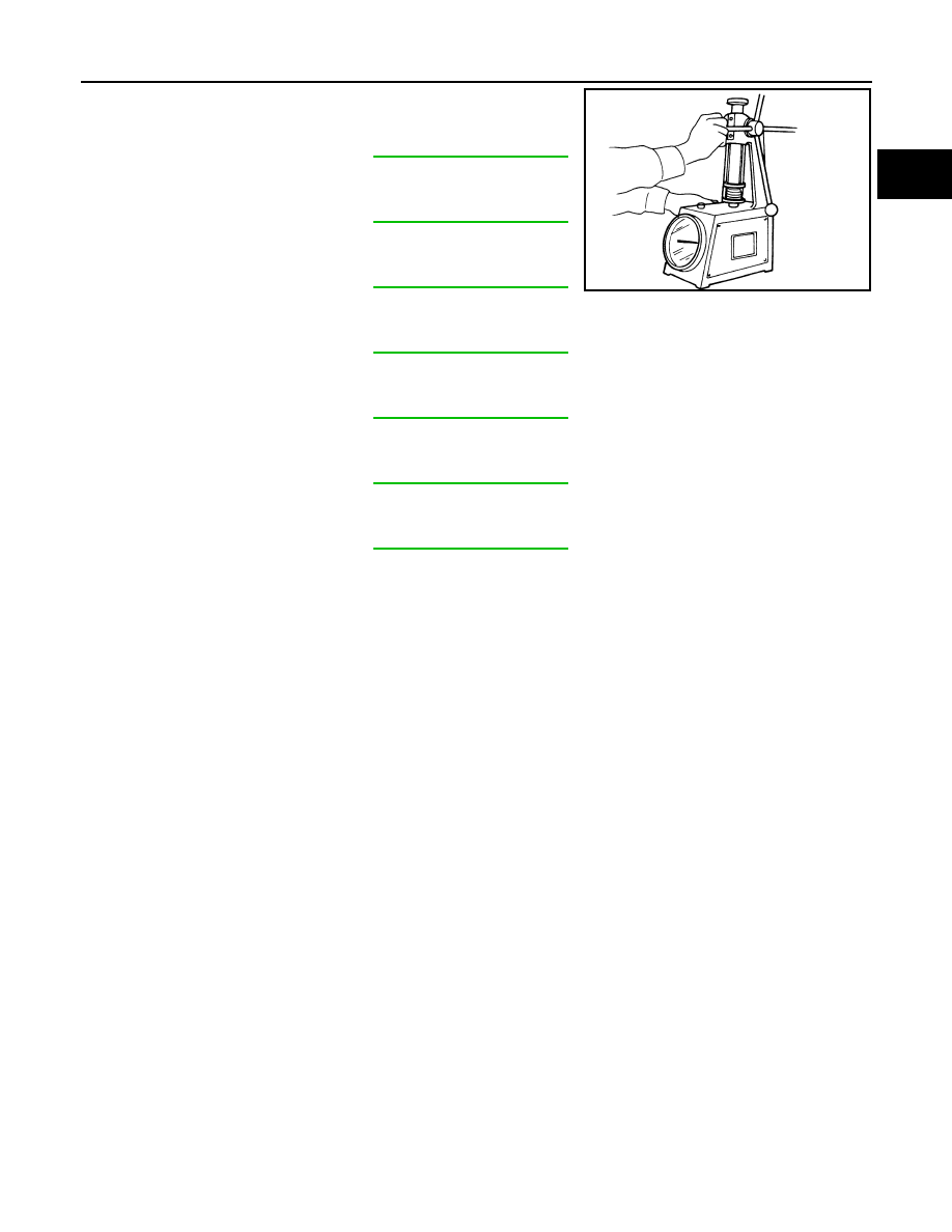
Valve Guide Clearance
1.
Measure diameter of valve stem with micrometer.
2.
Measure inner diameter of valve guide with inside micrometer.
3.
Calculate the valve guide clearance.
(Valve guide clearance) = (Valve guide inner diameter) – (Valve
stem diameter)
• If it exceeds the limit, replace and/or valve guide.
Valve Spring
Intake
: Refer to
Exhaust
Intake
: Refer to
Exhaust
Intake
: Refer to
Exhaust
Intake
: Refer to
Exhaust
Intake
: Refer to
Exhaust
Intake
: Refer to
Exhaust
Intake
: Refer to
Exhaust
E1BIA0066ZZ
Intake
: 0.020 - 0.050 mm (0.0008 - 0.0020 in)
Exhaust
: 0.030 - 0.063 mm (0.0012 - 0.0025 in)
SEM938C
CYLINDER HEAD
EM-309
< DISASSEMBLY AND ASSEMBLY >
[K9K]
C
D
E
F
G
H
I
J
K
L
M
A
EM
N
P
O
Measure the valve spring as follows.
• Free height
• Length under load
• Full pressed height
• Wire diameter
• Inner diameter
• Outer diameter
• Squareness
Intake and exhaust
: Refer to
Intake and exhaust
: Refer to
Intake and exhaust
: Refer to
Intake and exhaust
: Refer to
Intake and exhaust
: Refer to
Intake and exhaust
: Refer to
Intake and exhaust
: Refer to
SEM113

EM-310
< DISASSEMBLY AND ASSEMBLY >
[K9K]
CYLINDER BLOCK
CYLINDER BLOCK
Exploded View
INFOID:0000000001063240
Disassembly and Assembly
INFOID:0000000001063268
DISASSEMBLY
E1BIA0017GB
1.
Oil seal
2.
Crankshaft cover
3.
Gasket
4.
Cylinder block
5.
Oil seal
6
TDC pin plug
7.
Top ring
8.
Second ring
9.
Oil ring
10. Piston
11.
Piston pin
12. Snap ring
13. Connecting rod
14. Crankshaft pulley bolt
15. Crankshaft pulley
16. Crankshaft sprocket (timing belt)
17.
Crankshaft sprocket (oil pump drive
chain)
18. Crankshaft
19. Pilot bushing
20. Flywheel
21. Reinforcement plate
A.
25.0 N·m (2.6 kg-m, 18 ft-lb) and 47 degrees
B.
20.0 N·m (2.0 kg-m, 15 ft-lb) and 45 degrees
C.
120.0 N·m (12 kg-m, 89 ft-lb) and 95 degrees
D.
20.0 N·m (2.0 kg-m, 15 ft-lb) and 36 degrees
Refer to
for symbols in the figure.
CYLINDER BLOCK
EM-311
< DISASSEMBLY AND ASSEMBLY >
[K9K]
C
D
E
F
G
H
I
J
K
L
M
A
EM
N
P
O
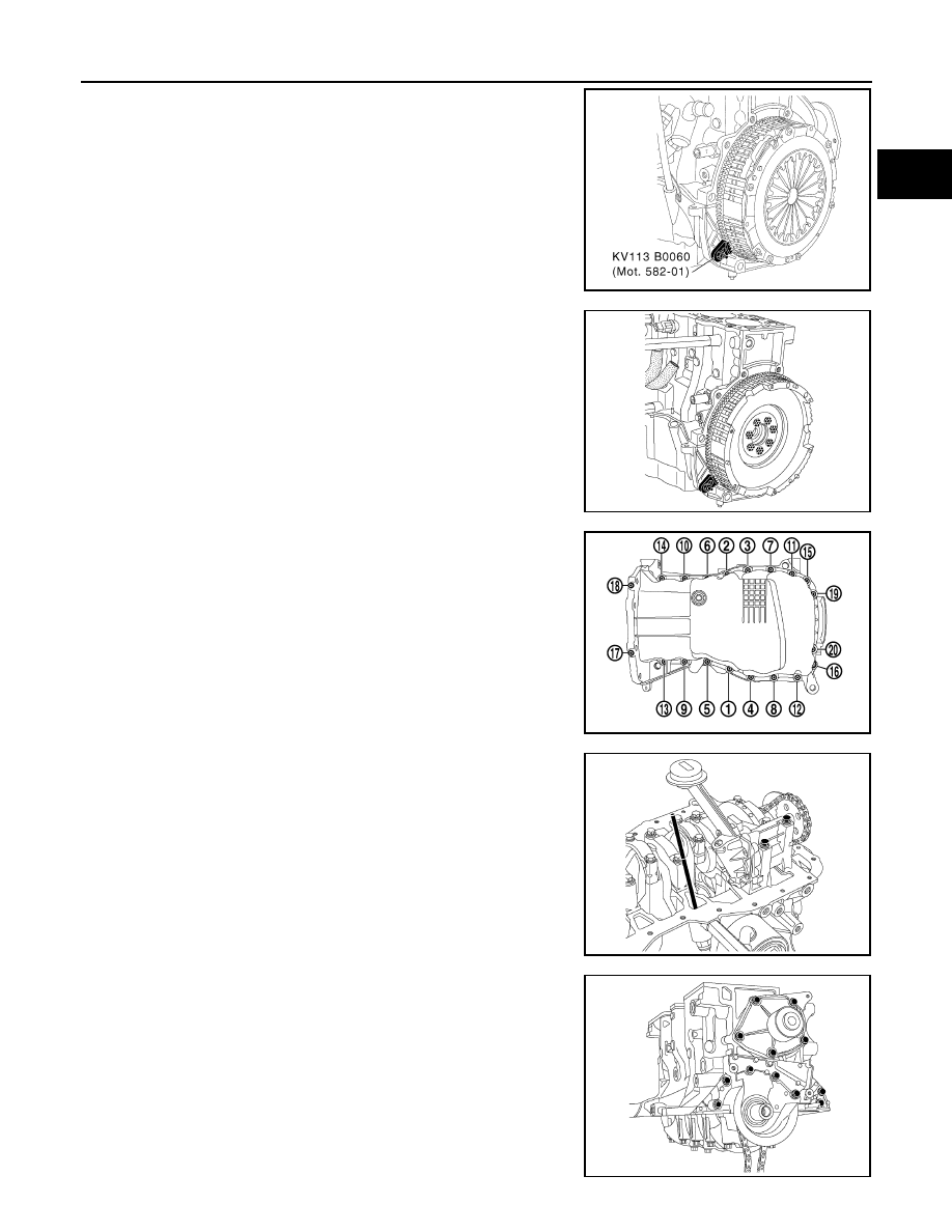
1.
Install the ring gear stopper [SST: KV113B0060 (Mot. 582-01)].
2.
Remove the clutch housing.
3.
Remove the flywheel.
4.
Remove the oil pan bolt in reverse order as shown.
5.
Remove the oil level sensor.
6.
Remove the oil pump.
7.
Remove the crankshaft cover.
8.
Remove the water pump.
MBIB0397E
MBIB0439E
MBIB1257E
MBIB0442E
MBIB0443E
Нет комментариевНе стесняйтесь поделиться с нами вашим ценным мнением.
Текст