Nissan Qashqai (2007-2010). Manual — part 349

COOLING FAN
EC-915
< COMPONENT DIAGNOSIS >
[MR20DE (WITH EURO-OBD)]
C
D
E
F
G
H
I
J
K
L
M
A
EC
N
P
O
COOLING FAN
Description
INFOID:0000000001089515
Cooling fan operates at each speed when the current flows in the cooling fan motor as follows.
Refer to
for cooling fan operation.
Component Function Check
INFOID:0000000001089516
1.
CHECK COOLING FAN LOW SPEED FUNCTION
With CONSULT-III
1.
Turn ignition switch ON.
2.
Perform “COOLING FAN” in “ACTIVE TEST” mode with CONSULT-III and touch “LOW” on the CON-
SULT-III screen.
3.
Make sure that cooling fans operates at low speed.
Without CONSULT-III
1.
Start engine and let it idle.
2.
Turn air conditioner switch and blower fan switch ON.
3.
Make sure that cooling fan operates at low speed.
Is the inspection result normal?
YES
>> GO TO 2.
NO
>> Check cooling fan low speed control circuit.
2.
CHECK COOLING FAN HIGH SPEED FUNCTION
With CONSULT-III
1.
Touch “HI” on the CONSULT-III screen.
2.
Make sure that cooling fans operates at higher speed than low speed.
Without CONSULT-III
1.
Turn ignition switch OFF.
2.
Turn air conditioner switch and blower fan switch OFF.
3.
Disconnect engine coolant temperature sensor harness connector.
4.
Connect 150
Ω
resistor to engine coolant temperature sensor harness connector.
5.
Restart engine and make sure that cooling fan operates at higher speed than low speed.
Is the inspection result normal?
YES
>> INSPECTION END
NO
>> Check cooling fan high speed control circuit.
Diagnosis Procedure
INFOID:0000000001089517
1.
CHECK POWER SUPPLY CIRCUIT
1.
Turn ignition switch OFF.
2.
Disconnect IPDM E/R harness connector and cooling fan relay-3 harness connector.
3.
Check the voltage between IPDM E/R harness connector or cooling fan relay-3 harness connector and
ground.
Is the inspection result normal?
YES
>> GO TO 3.
NO
>> GO TO 2.
2.
DETECT MALFUNCTIONING PART
Check the following.
IPDM E/R
cooling fan relay-3
Ground
Voltage
Connector
Terminal
Connec-
tor
Terminal
E14
53
E59
1
Ground
Battery voltage
3
EC-916
< COMPONENT DIAGNOSIS >
[MR20DE (WITH EURO-OBD)]
COOLING FAN
• 50A fusible link (letter M)
• Harness for open or short between IPDM E/R cooling fan relay-3 and battery
>> Repair or replace malfunctioning part.
3.
CHECK COOLING FAN MOTORS CIRCUIT FOR OPEN AND SHORT
1.
Disconnect cooling fan motor harness connector.
2.
Check the continuity between IPDM E/R harness connector or cooling fan relay-3 harness connector and
cooling fan motor harness connector.
3.
Check the continuity between cooling fan relay-3 harness connector and IPDM E/R harness connector.
4.
Check the continuity between cooling fan motor harness connector or IPDM E/R harness connector and
ground.
5.
Also check harness for short to ground and short to power.
Is the inspection result normal?
YES
>> GO TO 5.
NO
>> GO TO 4.
4.
DETECT MALFUNCTIONING PART
Check the following.
• Harness for open or short between cooling fan motor and IPDM E/R
• Harness for open or short between cooling fan motor and cooling fan relay
• Harness for open or short between cooling fan relay-3 and IPDM E/R
• Harness for open or short between cooling fan motor and ground
• Harness for open or short between IPDM E/R and ground
• Resistor E57
>> Repair or replace malfunctioning part.
5.
CHECK GROUND CONNECTION
Check ground connection E21. Refer to Ground Inspection in
.
Is the inspection result normal?
YES
>> GO TO 6.
NO
>> Repair or replace ground connection.
6.
CHECK COOLING FAN RELAYS
EC-920, "Component Inspection (Cooling Fan Relay)"
Is the inspection result normal?
YES
>> GO TO 7.
NO
>> Replace malfunctioning cooling fan relay.
Cooling fan relay-3
IPDM E/R
Cooling fan motor
Continuity
Connector
Terminal
Connector
Terminal
Connec-
tor
Terminal
E59
2
E14
52
E3
1
Existed
Cooling fan relay-3
IPDM E/R
Continuity
Connector
Terminal
Connector
Terminal
E59
4
E13
48
Existed
Cooling fan motor
IPDM E/R
Ground
Continuity
Connector
Terminal
Connector
Terminal
E3
2
E10
5
Ground
Existed
6
COOLING FAN
EC-917
< COMPONENT DIAGNOSIS >
[MR20DE (WITH EURO-OBD)]
C
D
E
F
G
H
I
J
K
L
M
A
EC
N
P
O
7.
CHECK COOLING FAN MOTOR
EC-920, "Component Inspection (Cooling Fan Motor)"
Is the inspection result normal?
YES
>> GO TO 8.
NO
>> Replace malfunctioning cooling fan motor.
8.
CHECK INTERMITTENT INCIDENT
Perform
GI-39, "Intermittent Incident"
.
Is the inspection result normal?
YES
>> Replace IPDM E/R.
NO
>> Repair or replace harness or connector.
Component Inspection (Cooling Fan Motor)
INFOID:0000000001089518
1.
CHECK COOLING FAN MOTOR
1.
Turn ignition switch OFF.
2.
Disconnect cooling fan motor harness connector.
3.
Supply cooling fan motor terminals with battery voltage and check operation.
Is the inspection result normal?
YES
>> INSPECTION END
NO
>> Replace cooling fan motor.
Component Inspection (Cooling Fan Relay)
INFOID:0000000001089519
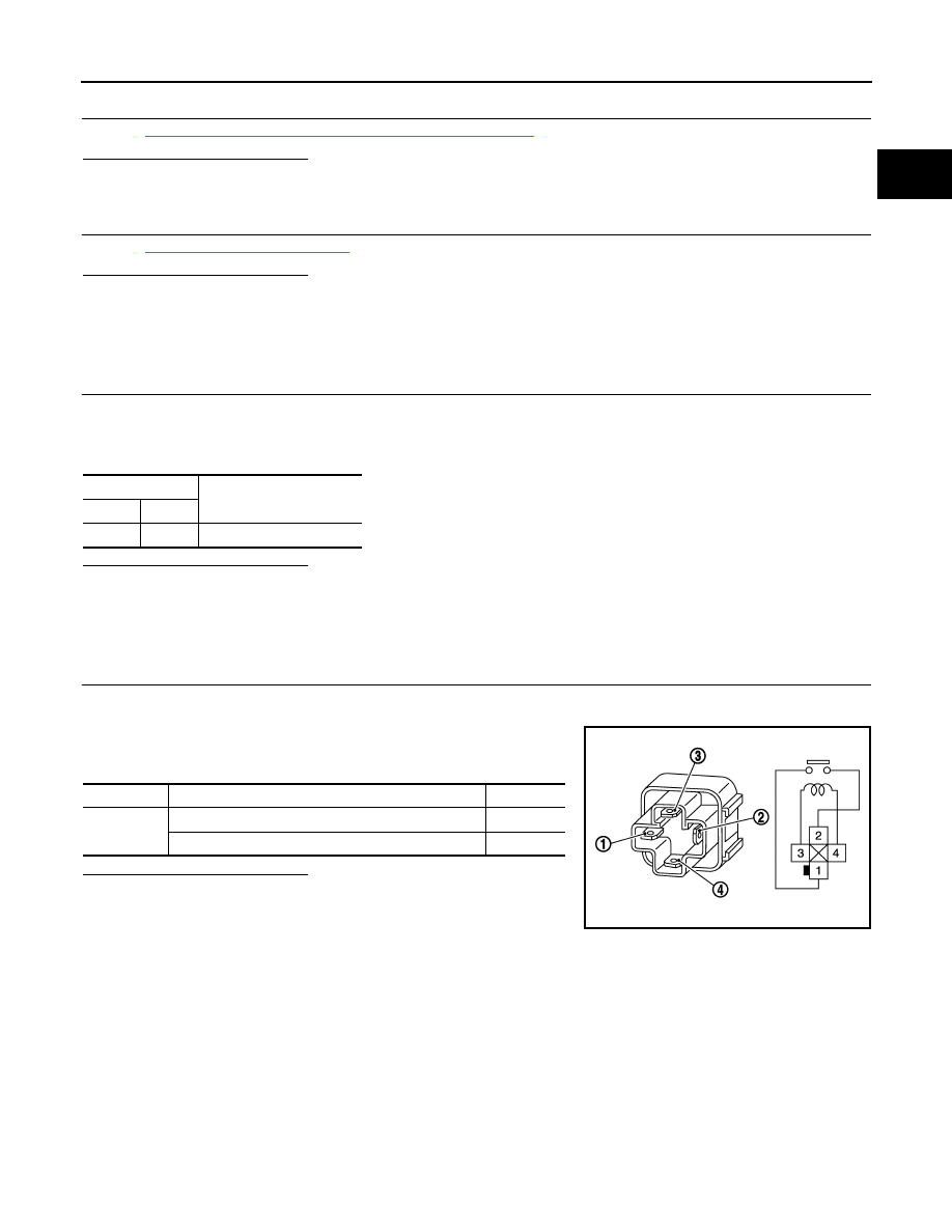
1.
CHECK COOLING FAN RELAY
1.
Turn ignition switch OFF.
2.
Remove cooling fan relay-3.
3.
Check the continuity between cooling fan relay terminals under
the following conditions.
Is the inspection result normal?
YES
>> INSPECTION END
NO
>> Replace cooling fan relay.
Terminals
Operation
(+)
(–)
1
2
Cooling fans operates .
Terminals
Conditions
Continuity
1 and 2
12V direct current supply between terminals 1 and 2
Existed
No current supply
Not existed
JMBIA0452ZZ
EC-918
< COMPONENT DIAGNOSIS >
[MR20DE (WITH EURO-OBD)]
ELECTRICAL LOAD SIGNAL
ELECTRICAL LOAD SIGNAL
Description
INFOID:0000000001089520
The electrical load signal (Headlamp switch signal, rear window defogger switch signal, etc.) is transferred
through the CAN communication line from BCM to ECM via IPDM E/R.
Component Function Check
INFOID:0000000001089521
1.
CHECK REAR WINDOW DEFOGGER SWITCH FUNCTION
1.
Turn ignition switch ON.
2.
Connect CONSULT-III and select “DATA MONITOR” mode.
3.
Select “LOAD SIGNAL” and check indication under the following conditions.
Is the inspection result normal?
YES
>> GO TO 2.
NO
>> Go to
2.
CHECK LIGHTING SWITCH FUNCTION
Check “LOAD SIGNAL” indication under the following conditions.
Is the inspection result normal?
YES
>> GO TO 3.
NO
>> Go to
3.
CHECK HEATER FAN CONTROL SWITCH FUNCTION
Select “HEATER FAN SW” and check indication under the following conditions.
Is the inspection result normal?
YES
>> INSPECTION END
NO
>> Go to
Diagnosis Procedure
INFOID:0000000001089522
1.
INSPECTION START
Confirm the malfunctioning circuit (rear window defogger, headlamp or heater fan). Refer to
Which circuit is related to the incident?
Rear window defogger>>GO TO 2
Headlamp>>GO TO 3.
Heater fan>>GO TO 4.
2.
CHECK REAR WINDOW DEFOGGER SYSTEM
Monitor item
Condition
Indication
LOAD SIGNAL
Rear window defogger switch
ON
ON
OFF
OFF
Monitor item
Condition
Indication
LOAD SIGNAL
Lighting switch
ON at 2nd position
ON
OFF
OFF
Monitor item
Condition
Indication
HEATER FAN SW
Heater fan control switch
ON
ON
OFF
OFF
Нет комментариевНе стесняйтесь поделиться с нами вашим ценным мнением.
Текст