Nissan Qashqai (2007-2010). Manual — part 133
ELECTRIC IGNITION SYSTEM
EC-51
< FUNCTION DIAGNOSIS >
[HR16DE (WITH EURO-OBD)]
C
D
E
F
G
H
I
J
K
L
M
A
EC
N
P
O
PBIB2942E
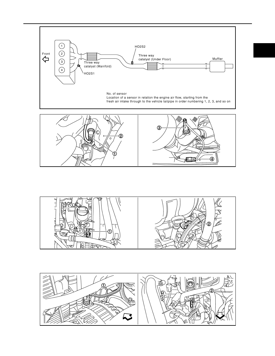
1.
Heated oxygen sensor 1
2.
Exhaust manifold cover
3.
Heated oxygen sensor 2
4.
Heated oxygen sensor 2 harness
connector
1.
Intake valve timing control solenoid
valve
2.
Knock sensor
1.
Refrigerant pressure sensor
2.
PCV valve
Vehicle front
JMBIA0406ZZ
JMBIA0404ZZ
JMBIA0405ZZ
EC-52
< FUNCTION DIAGNOSIS >
[HR16DE (WITH EURO-OBD)]
ELECTRIC IGNITION SYSTEM
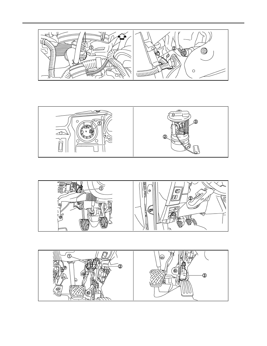
1.
Cooling fan motor
2.
Crankshaft position sensor (POS)
Vehicle front
1.
Fuel level sensor unit and fuel pump
harness connector
2.
Fuel level sensor unit and fuel pump 3.
Fuel pressure regulator
1.
ASCD clutch switch
2.
Data link connector
1.
Stop lamp switch
2.
ASCD brake pedal
3.
Accelerator pedal position sensor
JMBIA0407ZZ
JMBIA0346ZZ
JMBIA0347ZZ
JMBIA0348ZZ
ELECTRIC IGNITION SYSTEM
EC-53
< FUNCTION DIAGNOSIS >
[HR16DE (WITH EURO-OBD)]
C
D
E
F
G
H
I
J
K
L
M
A
EC
N
P
O
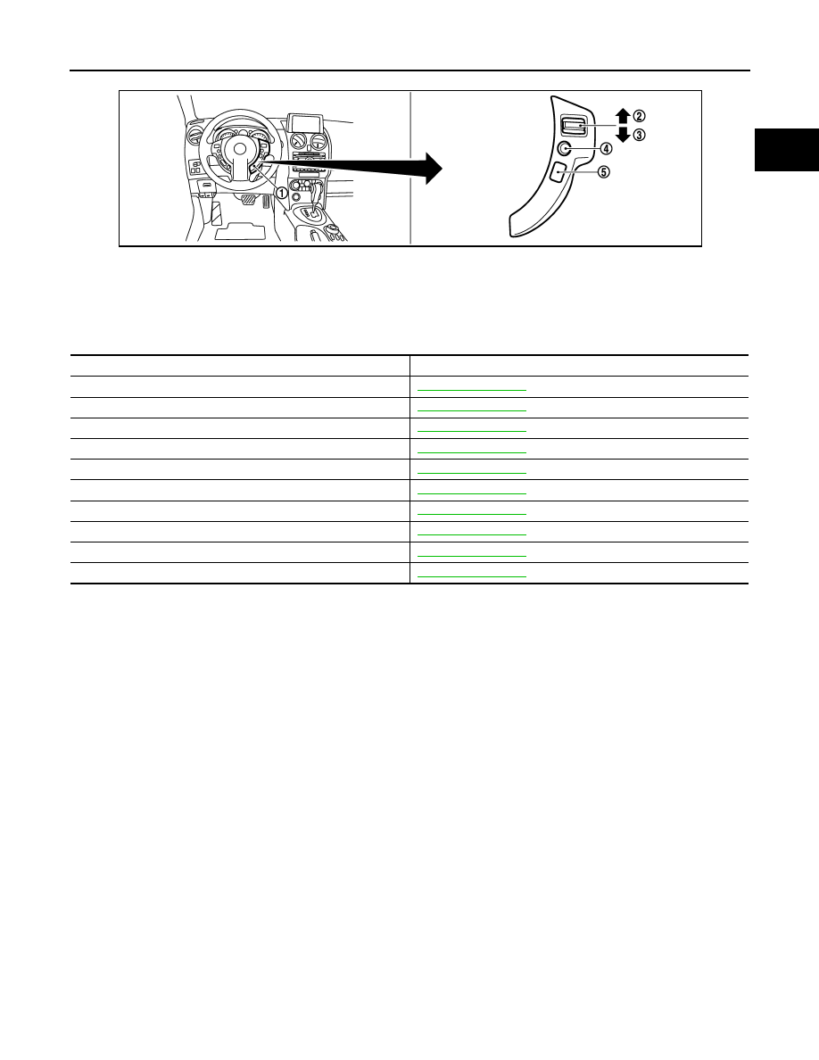
Component Description
INFOID:0000000001056140
1.
ASCD steering switch
2.
CANSEL switch
3.
RESUME/ACCELERATE switch
4.
SET/COAST switch
5.
MAIN switch
JMBIA0349ZZ
Component
Reference
Accelerator pedal position sensor
Camshaft position sensor (PHASE)
Crankshaft position sensor (POS)
Engine coolant temperature sensor
Ignition signal
Knock sensor
Mass air flow sensor
Park/neutral position (PNP) switch
Throttle position sensor
Vehicle speed sensor
EC-54
< FUNCTION DIAGNOSIS >
[HR16DE (WITH EURO-OBD)]
AIR CONDITIONING CUT CONTROL
AIR CONDITIONING CUT CONTROL
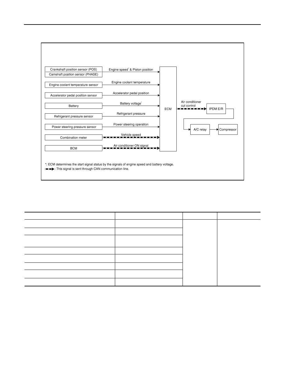
System Diagram
INFOID:0000000001056141
System Description
INFOID:0000000001056142
INPUT/OUTPUT SIGNAL CHART
*1: This signal is sent to the ECM through CAN communication line.
*2: ECM determines the start signal status by the signals of engine speed and battery voltage.
SYSTEM DESCRIPTION
This system improves engine operation when the air conditioner is used.
Under the following conditions, the air conditioner is turned off.
• When the accelerator pedal is fully depressed.
• When cranking the engine.
• At high engine speeds.
• When the engine coolant temperature becomes excessively high.
• When operating power steering during low engine speed or low vehicle speed.
• When engine speed is excessively low.
• When refrigerant pressure is excessively low or high.
JMBIA0175GB
Sensor
Input Signal to ECM
ECM function
Actuator
BCM*
1
Air conditioner ON signal
Air conditioner
cut control
IPDM E/R
↓
Air conditioner relay
↓
Compressor
Accelerator pedal position sensor
Accelerator pedal position
Crankshaft position sensor (POS)
Camshaft position sensor (PHASE)
Engine speed*
2
Engine coolant temperature sensor
Engine coolant temperature
Battery
Battery voltage*
2
Refrigerant pressure sensor
Refrigerant pressure
EPS control unit*
1
Power steering operation
Combination meter*
1
Vehicle speed
Нет комментариевНе стесняйтесь поделиться с нами вашим ценным мнением.
Текст