Nissan Qashqai (2007-2010). Manual — part 546
CONTROL LINKAGE
TM-119
< ON-VEHICLE REPAIR >
[6MT: RS6F52A]
C
E
F
G
H
I
J
K
L
M
A
B
TM
N
O
P
3.
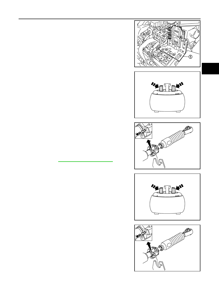
Disconnect connectors (A) and then remove bracket (1).
4.
While pressing the lock of the select cable in the direction of the
arrow shown in the figure, remove the select cable from the
selector lever.
5.
While pressing the lock of the shift cable in the direction of the
arrow shown in the figure, remove the shift cable from the shifter
lever A.
6.
While pulling the lock of the select cable in the direction of the
arrow shown in the figure, remove the select cable from the
cable mounting bracket.
7.
While pulling the lock of the shift cable in the direction of the
arrow shown in the figure, remove the shift cable from the cable
mounting bracket.
8.
Remove the control lever knob.
9.
Remove console finisher assembly and the center console
assembly. Refer to
IP-18, "Removal and Installation"
.
10. Shift the control lever to the neutral position.
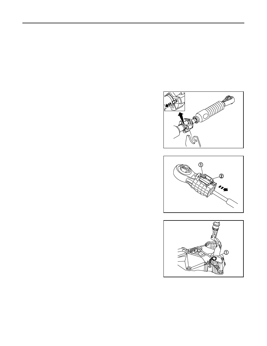
11. While pressing the lock of the select cable in the direction of the
arrow shown in the figure, remove the select cable from the con-
trol device assembly.
12. While pressing the lock of the shift cable in the direction of the
arrow shown in the figure, remove the shift cable from the con-
trol device assembly.
13. While pulling the lock of the select cable in the direction of the
arrow shown in the figure, remove the select cable from the con-
trol device assembly.
14. While pulling the lock of the shift cable in the direction of the
arrow shown in the figure, remove the shift cable from the con-
trol device assembly.
15. Remove the control device assembly.
16. Remove the heat plate.
17. Remove the bracket.
JPDIA0240ZZ
JPDIC0066ZZ
JPDIC0067ZZ
JPDIC0066ZZ
JPDIC0067ZZ
TM-120
< ON-VEHICLE REPAIR >
[6MT: RS6F52A]
CONTROL LINKAGE
18. Remove the grommet and then remove the shift cable and select cable from the vehicle.
INSTALLATION
Note the following, and install in the reverse order of removal.
• Shift the control lever to the neutral position.
• Securely assemble each cable and the selector lever and shifter lever A.
• Securely assemble each cable and the cable mounting bracket.
• Securely assemble each cable and the control device assembly.
• Make sure that the claws of grommet are in contact with the floor.
• Be careful about the installation direction and push the control lever knob into the control lever.
CAUTION:
Never reuse control lever knob.
Install the select cable (the control device assembly side) with the following procedure.
1.
While pulling the lock of the select cable in the direction of the
arrow shown in the figure, install the select cable to the control
device assembly.
2.
Slide the lock (1) of the select cable in the direction of the arrow
as shown in the figure to pull up the stopper (2) of the select
cable.
3.
Install the end of the select cable to the pin of the control device
assembly.
4.
Install the lever stopper pin (1) or a pin [3 mm (0.12 in) dia.] to
the control device assembly.
CAUTION:
Select cable cannot be adjusted accurately without a use of
a lever stopper pin or a pin [3 mm (0.12 in) dia.].
NOTE:
A lever stopper pin is not included in control device assembly.
Therefore, if the control device assembly is not replaced, pre-
pare a pin [3 mm (0.12 in) dia.].
5.
Check that the control lever does not move in the direction of the
select. If it moves, repeat step 3.
6.
Shift the control lever to 4th gear position.
JPDIC0067ZZ
JPDIC0064ZZ
JPDIC0069ZZ
CONTROL LINKAGE
TM-121
< ON-VEHICLE REPAIR >
[6MT: RS6F52A]
C
E
F
G
H
I
J
K
L
M
A
B
TM
N
O
P
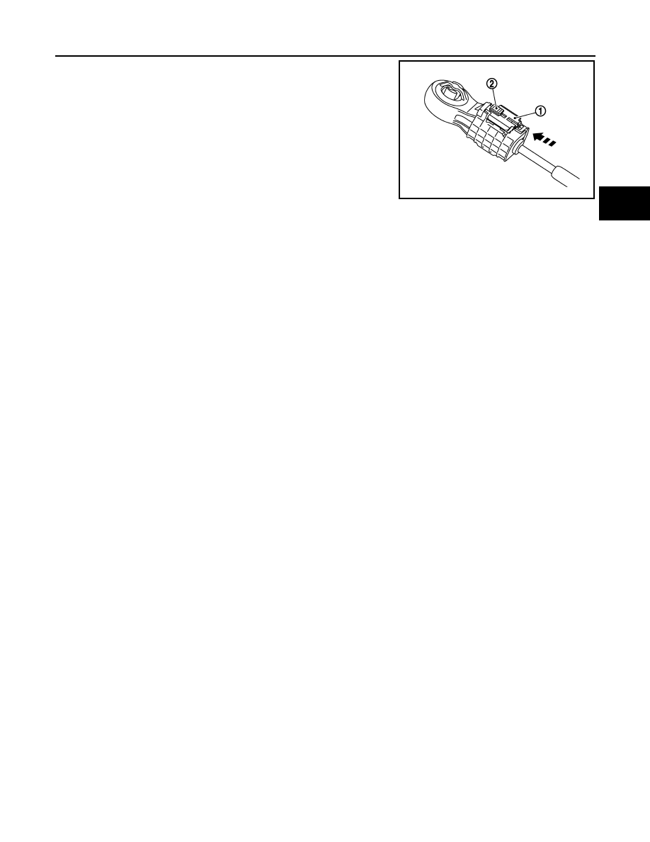
7.
With the stopper (1) of the select cable pressed into all the way,
slide lock (2) of the select cable all the way in the direction of the
arrow.
8.
Remove the lever stopper pin or a pin [3 mm (0.12 in) dia.] from
the control device assembly.
9.
Shift the control lever to each gear position to check that there is
no bindings. If any, repeat step 3.
Inspection
INFOID:0000000001034946
After installing, confirm the following items:
• When the control lever is shifted to 1st-2nd side and 5th-6th side, confirm the control lever returns to neutral
position smoothly.
• When the control lever is shifted to each position, make sure there is no binding or disconnection in each
boot.
JPDIC0065ZZ
TM-122
< ON-VEHICLE REPAIR >
[6MT: RS6F52A]
AIR BREATHER HOSE
AIR BREATHER HOSE
Exploded View
INFOID:0000000001034947
Removal and Installation
INFOID:0000000001034948
REMOVAL
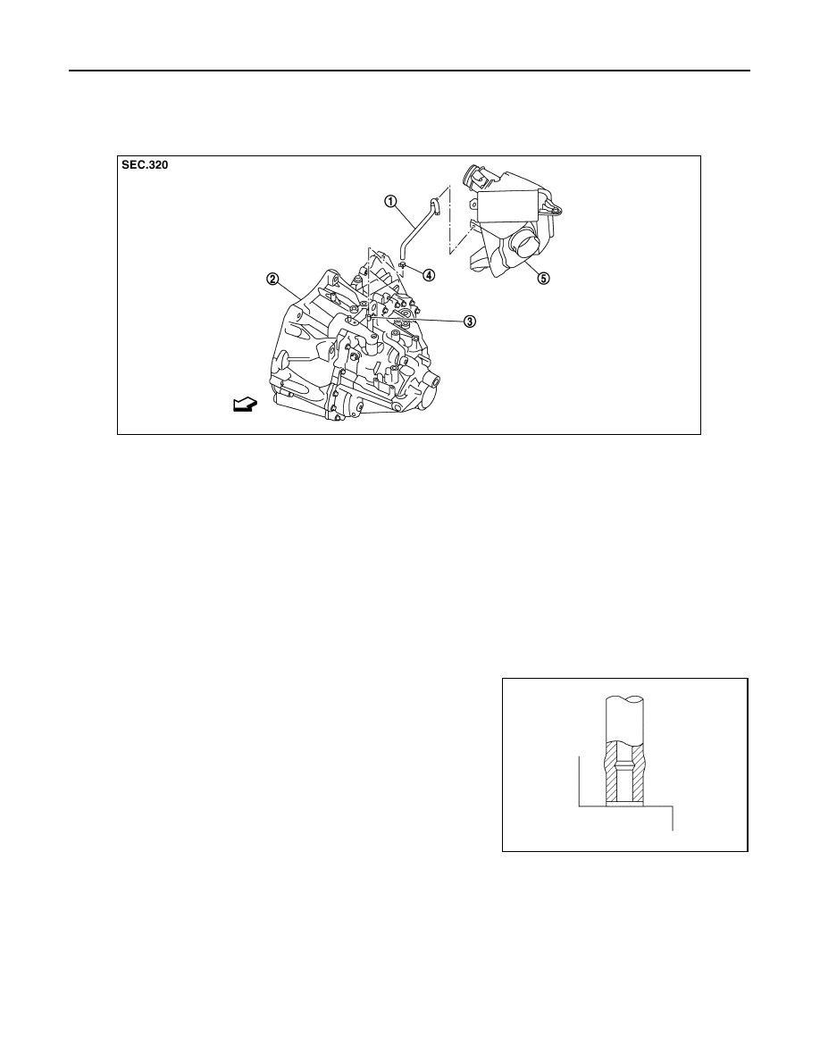
Refer to the figure for removal procedure.
INSTALLATION
Refer to the figure for installation procedure.
CAUTION:
• Make sure there are no pinched or restricted areas on the air breather hose caused by bending or
winding when installing it.
• Be sure to insert air breather hose into air breather tube until
hose end reaches the tube's base.
• Set air breather hose with painted mark facing forward.
• Install air breather hose to air cleaner case by fully inserting
the clip.
1.
Air breather hose
2.
Transaxle assembly
3.
Air breather tube
4.
Clamp
5.
Air cleaner case
: Vehicle front
JPDIC0051ZZ
SCIA2663J
Нет комментариевНе стесняйтесь поделиться с нами вашим ценным мнением.
Текст