Nissan Qashqai (2007-2010). Manual — part 421
IAT SENSOR
EC-1203
< COMPONENT DIAGNOSIS >
[MR20DE (WITHOUT EURO-OBD)]
C
D
E
F
G
H
I
J
K
L
M
A
EC
N
P
O
Is the inspection result normal?
YES
>> GO TO 3.
NO
>> Repair open circuit or short to ground or short to power in harness or connectors.
3.
CHECK INTAKE AIR TEMPERATURE SENSOR GROUND CIRCUIT FOR OPEN AND SHORT
1.
Turn ignition switch OFF.
2.
Disconnect ECM harness connector.
3.
Check the continuity between mass air flow sensor harness connector and ECM harness connector.
4.
Also check harness for short to ground and short to power.
Is the inspection result normal?
YES
>> GO TO 4.
NO
>> Repair open circuit or short to ground or short to power in harness or connectors.
4.
CHECK INTAKE AIR TEMPERATURE SENSOR
EC-1207, "Component Inspection"
.
Is the inspection result normal?
YES
>> GO TO 5.
NO
>> Replace mass air flow sensor (with intake air temperature sensor).
5.
CHECK INTERMITTENT INCIDENT
GI-39, "Intermittent Incident"
.
>> INSPECTION END
Component Inspection
INFOID:0000000001102136
1.
CHECK INTAKE AIR TEMPERATURE SENSOR
1.
Turn ignition switch OFF.
2.
Disconnect mass air flow sensor harness connector.
3.
Check resistance between mass air flow sensor terminals as follows.
Is the inspection result normal?
YES
>> INSPECTION END
NO
>> Replace mass air flow sensor (with intake air temperature sensor).
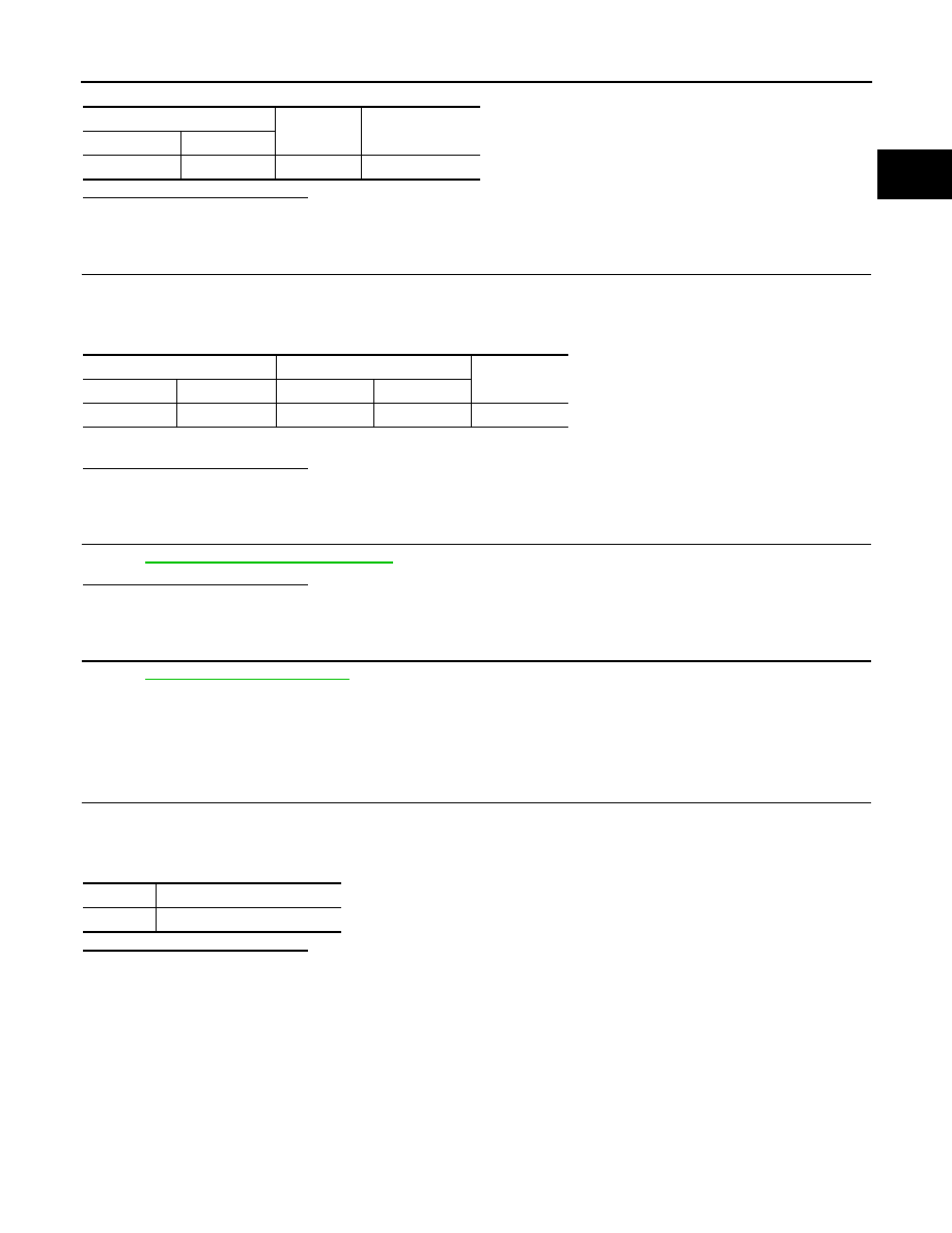
MAF sensor
Ground
Voltage
Connector
Terminal
E18
2
Ground
Approx. 5V
MAF sensor
ECM
Continuity
Connector
Terminal
Connector
Terminal
E18
1
F8
55
Existed
Terminals
Resistance [
°
C (77
°
F)]
1 and 2
1.800 - 2.200 k
Ω
EC-1204
< COMPONENT DIAGNOSIS >
[MR20DE (WITHOUT EURO-OBD)]
IGNITION SIGNAL
IGNITION SIGNAL
Description
INFOID:0000000001094308
The ignition signal from the ECM is sent to and amplified by the power transistor. The power transistor turns
ON and OFF the ignition coil primary circuit. This ON/OFF operation induces the proper high voltage in the coil
secondary circuit.
Component Function Check
INFOID:0000000001094309
1.
INSPECTION START
Turn ignition switch OFF, and restart engine.
Does the engine start?
YES-1 >> With CONSULT-III: GO TO 2.
YES-2 >> Without CONSULT-III: GO TO 3.
NO
>> Go to
EC-1208, "Diagnosis Procedure"
2.
IGNITION SIGNAL FUNCTION
With CONSULT-III
1.
Perform “POWER BALANCE” in “ACTIVE TEST” mode with CONSULT-III.
2.
Make sure that each circuit produces a momentary engine speed drop.
Is the inspection result normal?
YES
>> INSPECTION END
NO
>> Go to
EC-1208, "Diagnosis Procedure"
3.
IGNITION SIGNAL FUNCTION
Without CONSULT-III
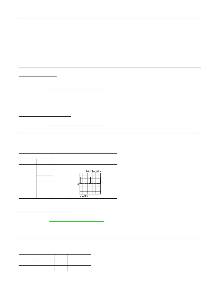
1.
Let engine idle.
2.
Read the voltage signal between ECM harness connector and ground.
NOTE:
The pulse cycle changes depending on rpm at idle.
Is the inspection result normal?
YES
>> INSPECTION END
NO
>> Go to
EC-1208, "Diagnosis Procedure"
Diagnosis Procedure
INFOID:0000000001094310
1.
CHECK IGNITION COIL POWER SUPPLY CIRCUIT-I
1.
Turn ignition switch OFF, wait at least 10 seconds and then turn ON.
2.
Check the voltage between ECM harness connector and ground.
ECM
Ground
Voltage signal
Connector
Terminal
F7
17
Ground
18
21
22
JMBIA0085GB
ECM
Ground
Voltage
Connector
Terminal
E16
105
Ground
Battery voltage
IGNITION SIGNAL
EC-1205
< COMPONENT DIAGNOSIS >
[MR20DE (WITHOUT EURO-OBD)]
C
D
E
F
G
H
I
J
K
L
M
A
EC
N
P
O
Is the inspection result normal?
YES
>> GO TO 2.
NO
>> Go to
2.
CHECK IGNITION COIL POWER SUPPLY CIRCUIT-II
1.
Turn ignition switch OFF.
2.
Disconnect condenser harness connector.
3.
Turn ignition switch ON.
4.
Check the voltage between condenser harness connector and ground.
Is the inspection result normal?
YES
>> GO TO 4.
NO
>> GO TO 3.
3.
CHECK IGNITION COIL POWER SUPPLY CIRCUIT-III
1.
Turn ignition switch OFF.
2.
Disconnect IPDM E/R harness connector F10.
3.
Check the continuity between IPDM E/R harness connector and condenser harness connector.
4.
Also check harness for short to ground and short to power.
Is the inspection result normal?
YES
>> Go to
NO
>> Repair open circuit or short to ground or short to power in harness or connectors.
4.
CHECK CONDENSER-2 GROUND CIRCUIT FOR OPEN AND SHORT
1.
Turn ignition switch OFF.
2.
Check the continuity between condenser harness connector and ground.
3.
Also check harness for short to power.
Is the inspection result normal?
YES
>> GO TO 5.
NO
>> Repair open circuit or short to ground or short to power in harness or connectors.
5.
CHECK CONDENSER
EC-1211, "Component Inspection (Condenser)"
Is the inspection result normal?
YES
>> GO TO 6.
NG
>> Replace condenser.
6.
CHECK IGNITION COIL POWER SUPPLY CIRCUIT-V
1.
Reconnect all harness connectors disconnected.
2.
Disconnect ignition coil harness connector.
3.
Turn ignition switch ON.
4.
Check the voltage between ignition coil harness connector and ground.
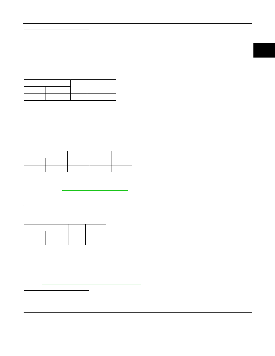
Condenser
Ground
Voltage
Connector
Terminal
F13
1
Ground
Battery voltage
IPDM E/R
Condenser
Continuity
Connector
Terminal
Connector
Terminal
E11
9
F13
1
Existed
Condenser
Ground
Continuity
Connector
Terminal
F13
2
Ground
Existed
EC-1206
< COMPONENT DIAGNOSIS >
[MR20DE (WITHOUT EURO-OBD)]
IGNITION SIGNAL
Is the inspection result normal?
YES
>> GO TO 7.
NO
>> Repair open circuit or short to ground or short to power in harness or connectors.
7.
CHECK IGNITION COIL GROUND CIRCUIT FOR OPEN AND SHORT
1.
Turn ignition switch OFF.
2.
Check the continuity between ignition coil harness connector and ground.
3.
Also check harness for short to power.
Is the inspection result normal?
YES
>> GO TO 8.
NO
>> Repair open circuit or short to ground or short to power in harness or connectors.
8.
CHECK IGNITION COIL OUTPUT SIGNAL CIRCUIT FOR OPEN AND SHORT
1.
Disconnect ECM harness connector.
2.
Check the continuity between ECM harness connector and ignition coil harness connector.
3.
Also check harness for short to ground and short to power.
Is the inspection result normal?
YES
>> GO TO 9.
NO
>> Repair open circuit or short to ground or short to power in harness or connectors.
9.
CHECK IGNITION COIL WITH POWER TRANSISTOR
EC-1211, "Component Inspection (Ignition Coil with Power Transistor)"
Is the inspection result normal?
YES
>> GO TO 10.
NO
>> Replace malfunctioning ignition coil with power transistor.
10.
CHECK INTERMITTENT INCIDENT
GI-39, "Intermittent Incident"
>> INSPECTION END
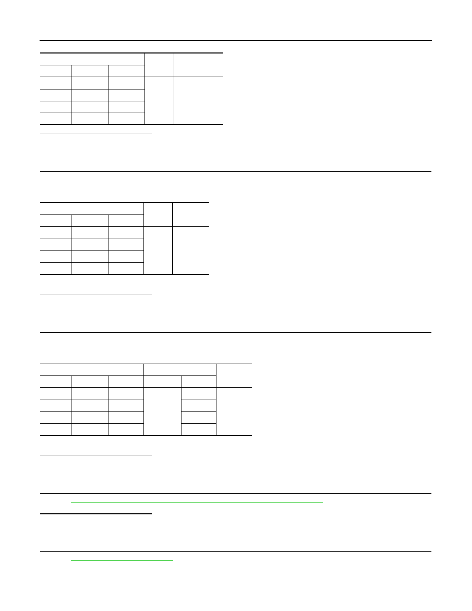
Ignition coil
Ground
Voltage
Cylinder
Connector
Terminal
1
F33
3
Ground
Battery voltage
2
F34
3
3
F35
3
4
F36
3
Ignition coil
Ground
Continuity
Cylinder
Connector
Terminal
1
F33
2
Ground
Existed
2
F34
2
3
F35
2
4
F36
2
Ignition coil
ECM
Continuity
Cylinder
Connector
Terminal
Connector
Terminal
1
F33
1
F7
17
Existed
2
F34
1
18
3
F35
1
22
4
F36
1
21
Нет комментариевНе стесняйтесь поделиться с нами вашим ценным мнением.
Текст