Nissan Qashqai (2007-2010). Manual — part 1187
PRE-INSPECTION FOR DIAGNOSTIC
DLK-827
< ON-VEHICLE MAINTENANCE >
[WITHOUT I-KEY, WITH SUPER LOCK]
C
D
E
F
G
H
I
J
L
M
A
B
DLK
N
O
P
ON-VEHICLE MAINTENANCE
PRE-INSPECTION FOR DIAGNOSTIC
Basic Inspection
INFOID:0000000001090935
BASIC INSPECTION
1.
CHECK DOOR LOCK AND UNLOCK SWITCH OPERATION
Check door lock and unlock operation by operating door lock and unlock switch.
Is the inspection result normal?
YES
>> GO TO 2.
NO
>> Refer to
DLK-812, "DOOR LOCK AND UNLOCK SWITCH : Symptom Table"
.
2.
CHECK KEYFOB OPERATION
Check door lock and unlock operation by operationg lock and unlock button of keyfob.
Is the inspection result normal?
YES
>> GO TO 3.
NO
>> Refer to
DLK-812, "KEYFOB : Symptom Table"
.
3.
CHECK AUTO DOOR LOCK OPERATION
Check auto door lock operation. Refer to
DLK-723, "AUTO DOOR LOCK : System Description"
Is the inspection result normal?
YES
>> GO TO 4.
NO
>> Refer to
DLK-813, "AUTO DOOR LOCK : Symptom Table"
4.
CHECK VEHICLE SPEED SENSING AUTO DOOR LOCK OPERATION
Check vehicle speed sensing auto door lock. Refer to
DLK-725, "VEHICLE SPEED SENSING AUTO DOOR
Is the inspection result normal?
YES
>> GO TO 5.
NO
>> Refer to
DLK-813, "VEHICLE SPEED SENSING AUTO DOOR LOCK : Symptom Table"
5.
CHECK BACK DOOR OPENER SWITCH OPERATION
Check back door opener operation by operating back door opener switch.
Is the inspection result normal?
YES
>> GO TO 6.
NO
>> Refer to
DLK-815, "BACK DOOR OPENER SWITCH : Symptom Table"
6.
CHECK HAZARD REMINDER FUNCTION
Check hazard reminder function by operating the following switches.
• Lock and unlock button of keyfob.
Is the inspection result normal?
YES
>> GO TO 7.
NO
>> Refer to
DLK-817, "HAZARD WARNING LAMP : Symptom Table"
7.
CHECK WARNING FUNCTION
Check that warning function operate properly. Refer to
.
Is the inspection result normal?
YES
>> GO TO 8.
NO
>> Refer to
DLK-817, "HAZARD WARNING LAMP : Symptom Table"
8.
CHECK OUT
CHECK OUT.
>> INSPECTION END
DLK-828
< ON-VEHICLE REPAIR >
[WITHOUT I-KEY, WITH SUPER LOCK]
HOOD
ON-VEHICLE REPAIR
HOOD
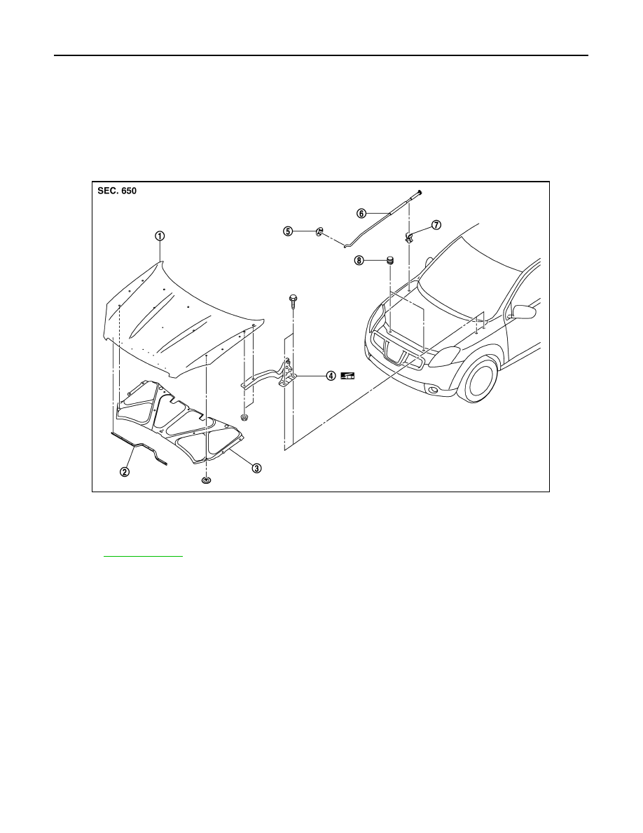
HOOD ASSEMBLY
HOOD ASSEMBLY : Exploded View
INFOID:0000000001098695
REMOVAL
ADJUSTMENT
1.
Hood assembly
2.
Hood sealing rubber
3.
Hood insulator
4.
Hood hinge
5.
Grommet
6.
Hood support rod
7.
Clamp
8.
Hood bumper rubber
Refer to
for symbols in the figure.
JMKIA0175ZZ
HOOD
DLK-829
< ON-VEHICLE REPAIR >
[WITHOUT I-KEY, WITH SUPER LOCK]
C
D
E
F
G
H
I
J
L
M
A
B
DLK
N
O
P
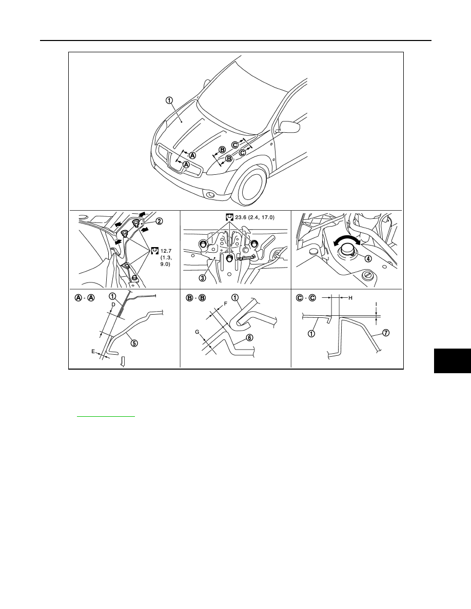
HOOD ASSEMBLY : Removal and Installation
INFOID:0000000001098696
REMOVAL
1.
Support the hood lock assembly with the proper material to prevent it from falling.
WARNING:
Bodily injury may occur if no supporting rod is holding the hood open when removing the hood
stay.
2.
Remove the hood hinge mounting nuts on the hood to remove the hood assembly.
CAUTION:
Perform work with 2 workers, because of its heavy weight.
3.
Remove the following parts after removing the hood assembly.
• Hood insulator
• Hood sealing rubber
INSTALLATION
Install in the reverse order of removal.
CAUTION:
1.
Hood assembly
2.
Hood hinge
3.
Hood lock assembly
4.
Hood bumper rubber
5.
Front grille
6.
Front combination lamp
7.
Front fender
Refer to
JMKIA0185GB
DLK-830
< ON-VEHICLE REPAIR >
[WITHOUT I-KEY, WITH SUPER LOCK]
HOOD
• Perform work with 2 workers, because of its heavy weight.
• Before installing the hood hinge, apply anticorrosive agent onto the mounting surface of the vehicle
body.
• After installing, perform hood fitting adjustment. Refer to
DLK-830, "HOOD ASSEMBLY : Adjust-
HOOD ASSEMBLY : Adjustment
INFOID:0000000001098697
1.
Check the clearance and the surface height between the hood and each part by visualy and touching.
(Fitting standard dimension in the table below should be satisfied.)
2.
In case any parts are out of specification, adjust them according to the procedures shown below.
3.
Remove the hood lock and adjust the height by rotating the bumper rubber until the hood becomes 1 to1.5
mm (0.04 to 0.059 in) lower than the fender.
4.
Temporarily tighten the hood lock, and position by engaging it with the hood striker. Check the lock and
striker for looseness and adjust the clearance and evenness with the striker to satisfy the specification.
5.
Adjust A and B shown in the figure to the following value with hood's own weight by dropping it from
approximately. 200 mm (7.87 in) height or by pressing the hood lightly [approximately. 29 N (3 kg)].
6.
After adjustment tighten lock bolts to the specified torque.
HOOD HINGE
Portion
Standard
Right/left
Clearance (MAX)
Hood – Front bumper
A – A
D
Clearance
5.2 – 9.2 mm
(0.205 – 0.362 in)
2.0 mm (0.079 in)
E
Surface height
- 0.2 – 3.8 mm
(- 0.008 – 0.150 in)
2.0 mm (0.079 in)
Hood –
Front combination lamp
B – B
F
Clearance
3.7 – 7.7 mm
(0.140 – 0.303 in)
2.0 mm (0.079 in)
G
Surface height
- 2.3 – 2.3 mm
(- 0.091 – 0.091 in)
2.3 mm (0.091 in)
Hood – Front fender
C – C
H
Clearance
3.9 – 5.9 mm
(0.154 – 0.232 in)
1.5 mm (0.059 in)
I
Surface height
- 1.0 – 1.0 mm
(- 0.039 – 0.039 in)
1.5 mm (0.059 in)
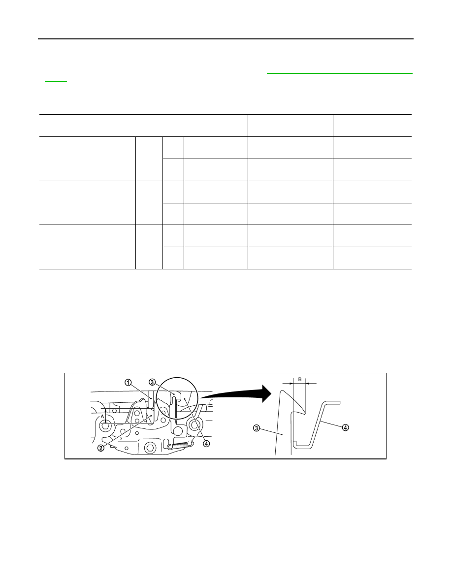
1.
Hood striker
2.
Primary latch
3.
Secondary striker
4.
Secondary latch
A
: 20.0 mm (0.787 in)
B
: 6.8 mm (0.268 in)
PIIB5794E
Нет комментариевНе стесняйтесь поделиться с нами вашим ценным мнением.
Текст