Nissan Qashqai (2007-2010). Manual — part 313
P0134 HO2S1
EC-771
< COMPONENT DIAGNOSIS >
[MR20DE (WITH EURO-OBD)]
C
D
E
F
G
H
I
J
K
L
M
A
EC
N
P
O
5.
Touch “RECORD” on CONSULT-III screen.
6.
Check the following.
-
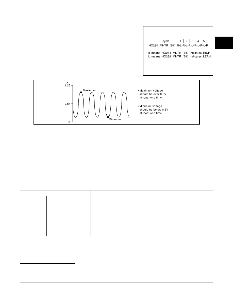
“HO2S1 MNTR (B1)” in “DATA MONITOR” mode changes from
“RICH” to “LEAN” to “RICH” more than 5 times in 10 seconds.
5 times (cycles) are counted as shown in the figure.
-
“HO2S1 (B1)” voltage goes above 0.6V at least once.
-
“HO2S1 (B1)” voltage goes below 0.3V at least once.
-
“HO2S1 (B1)” voltage never exceeds 1.0V.
CAUTION:
•
Discard any heated oxygen sensor which has been dropped from a height of more than 0.5 m
(19.7 in) onto a hard surface such as a concrete floor; use a new one.
•
Before installing new oxygen sensor, clean exhaust system threads using Oxygen Sensor
Thread Cleaner tool and approved anti-seize lubricant.
Is the inspection result normal?
YES
>> INSPECTION END
NO
>> GO TO 3.
3.
CHECK HEATED OXYGEN SENSOR 1
Without CONSULT-III
1.
Start engine and warm it up to normal operating temperature.
2.
Check the voltage between ECM harness connector and ground under the following condition.
CAUTION:
• Discard any heated oxygen sensor which has been dropped from a height of more than 0.5 m (19.7
in) onto a hard surface such as a concrete floor; use a new one.
• Before installing new oxygen sensor, clean exhaust system threads using Oxygen Sensor Thread
Cleaner tool and approved anti-seize lubricant.
Is the inspection result normal?
YES
>> INSPECTION END
NO
>> GO TO 4
4.
REPLACE HEATED OXYGEN SENSOR 1
Replace heated oxygen sensor 1.
SEF217YA
JMBIA0352ZZ
ECM
ground
Condition
Voltage
Connector
Terminal
F8
49
(HO2S1 signal)
Ground
Engine speed held at 2,000
rpm constant under no load.
• The voltage fluctuates between 0 to 0.3V and 0.6 to
1.0V more than 5 times within 10 seconds.
• The maximum voltage is over 0.6V at least 1 time.
• The minimum voltage is below 0.3V at least 1 time.
• The voltage never exceeds 1.0V.
1 time: 0 - 0.3V
→
0.6 - 1.0V
→
0 - 0.3V
2 times: 0 - 0.3V
→
0.6 - 1.0V
→
0 - 0.3V
→
0.6 - 1.0V
→
0 - 0.3V
EC-772
< COMPONENT DIAGNOSIS >
[MR20DE (WITH EURO-OBD)]
P0134 HO2S1
CAUTION:
• Discard any heated oxygen sensor which has been dropped from a height of more than 0.5 m (19.7
in) onto a hard surface such as a concrete floor; use a new one.
• Before installing new oxygen sensor, clean exhaust system threads using Oxygen Sensor Thread
Cleaner tool and approved anti-seize lubricant.
>> INSPECTION END

P0135 HO2S1 HEATER
EC-773
< COMPONENT DIAGNOSIS >
[MR20DE (WITH EURO-OBD)]
C
D
E
F
G
H
I
J
K
L
M
A
EC
N
P
O
P0135 HO2S1 HEATER
Description
INFOID:0000000001089348
SYSTEM DESCRIPTION
The ECM performs ON/OFF duty control of the heated oxygen sensor 1 heater corresponding to the engine
speed and engine coolant temperature. The duty percent varies with engine coolant temperature when engine
is started.
DTC Logic
INFOID:0000000001089349
DTC DETECTION LOGIC
DTC CONFIRMATION PROCEDURE
1.
PRECONDITIONING
If DTC Confirmation Procedure has been previously conducted, always turn ignition switch OFF and wait at
least 10 seconds before conducting the next test.
TESTING CONDITION:
Before performing the following procedure, confirm that battery voltage is more than between 11V at
idle.
>> GO TO 2.
2.
PERFORM DTC CONFIRMATION PROCEDURE
1.
Turn ignition switch ON.
2.
Select “DATA MONITOR” mode with CONSULT-III.
3.
Wait at least 5 seconds.
4.
Check 1st trip DTC.
Is 1st trip DTC detected?
YES
>> Go to
NO
>> INSPECTION END
Diagnosis Procedure
INFOID:0000000001089350
1.
CHECK GROUND CONNECTION
1.
Turn ignition switch OFF.
2.
Check ground connection E21. Refer to Ground Inspection in
.
Is the inspection result normal?
YES
>> GO TO 2.
NO
>> Repair or replace ground connection.
2.
CHECK HO2S1 POWER SUPPLY CIRCUIT
1.
Disconnect heated oxygen sensor 1 harness connector.
2.
Turn ignition switch ON.
3.
Check the voltage between HO2S1 sensor 1 harness connector and ground.
Sensor
Input Signal to ECM
ECM function
Actuator
Camshaft position sensor (PHASE)
Crankshaft position sensor (POS)
Engine speed
Heated oxygen sensor 1
heater control
Heated oxygen sensor 1
heater
Mass air flow sensor
Amount of intake air
DTC No.
Trouble diagnosis name
DTC detecting condition
Possible cause
P0135
Heated oxygen sensor 1
heater control circuit low
The current amperage in the heated oxygen sensor
1 heater circuit is out of the normal range.
(An excessively low voltage signal is sent to ECM
through the heated oxygen sensor 1 heater.)
• Harness or connectors
(The heated oxygen sensor 1 heater
circuit is open or shorted.)
• Heated oxygen sensor 1 heater

EC-774
< COMPONENT DIAGNOSIS >
[MR20DE (WITH EURO-OBD)]
P0135 HO2S1 HEATER
Is the inspection result normal?
YES
>> GO TO 4.
NO
>> GO TO 3.
3.
DETECT MALFUNCTIONING PART
Check the following.
• Harness connectors F123, E6
• 10A fuse (No. 56)
• Harness for open or short between heated oxygen sensor 1 and fuse
>> Repair or replace harness or connectors.
4.
CHECK HO2S1 OUTPUT SIGNAL CIRCUIT FOR OPEN AND SHORT
1.
Turn ignition switch OFF.
2.
Disconnect ECM harness connector.
3.
Check the continuity between HO2S1 harness connector and ECM harness connector.
4.
Also check harness for short to ground and short to power.
Is the inspection result normal?
YES
>> GO TO 5.
NO
>> Repair open circuit or short to ground or short to power in harness or connectors.
5.
CHECK HEATED OXYGEN SENSOR 1 HEATER
EC-776, "Component Inspection"
Is the inspection result normal?
YES
>> GO TO 7.
NO
>> GO TO 6.
6.
REPLACE HEATED OXYGEN SENSOR 1
Replace heated oxygen sensor 1.
>> INSPECTION END
7.
CHECK INTERMITTENT INCIDENT
Perform
GI-39, "Intermittent Incident"
.
>> Repair or replace.
Component Inspection
INFOID:0000000001089351
1.
CHECK HEATED OXYGEN SENSOR 1
1.
Turn ignition switch OFF.
2.
Disconnect HO2S1 harness connector.
3.
Check resistance between HO2S1 terminals as follows.
HO2S1
Ground
Voltage
Connector
Terminal
F30
2
Ground
Battery voltage
HO2S1
ECM
Continuity
Connector
Terminal
Connector
Terminal
F30
3
F7
3
Existed
Нет комментариевНе стесняйтесь поделиться с нами вашим ценным мнением.
Текст