Nissan Qashqai (2007-2010). Manual — part 1927
WCS-54
< ECU DIAGNOSIS >
BCM (BODY CONTROL MODULE)
34
(GR)
Ground
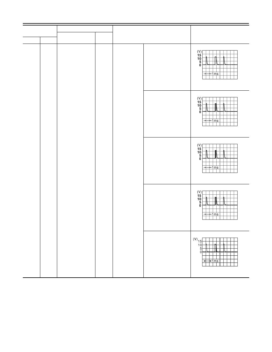
Combination switch
INPUT 4
Input
Combination
switch
All switch OFF
(Wiper intermittent dial 4)
1.4 V
Lighting switch AUTO
(Wiper intermittent dial 4)
1.3 V
Lighting switch 1ST
(Wiper intermittent dial 4)
1.3 V
Rear wiper INT
(Wiper intermittent dial 4)
1.3 V
Any of the condition below
with all switch OFF
• Wiper intermittent dial 1
• Wiper intermittent dial 6
1.3 V
Terminal No.
(Wire color)
Description
Condition
Value
(Approx.)
Signal name
Input/
Output
+
−
JPMIA0165GB
JPMIA0167GB
JPMIA0166GB
JPMIA0167GB
JPMIA0196GB
WCS
BCM (BODY CONTROL MODULE)
WCS-55
< ECU DIAGNOSIS >
C
D
E
F
G
H
I
J
K
L
M
B
A
O
P
35
(L)
Ground
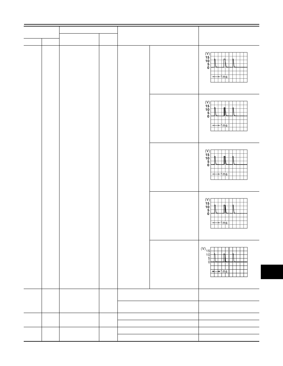
Combination switch
INPUT 3
Input
Combination
switch
All switch OFF
(Wiper intermittent dial 4)
1.4 V
Lighting switch HI
(Wiper intermittent dial 4)
1.3 V
Lighting switch 2ND
(Wiper intermittent dial 4)
1.3 V
Rear wiper switch ON
1.3 V
Any of the condition below
with all switch OFF
• Wiper intermittent dial 1
• Wiper intermittent dial 2
• Wiper intermittent dial 3
1.3 V
36
(V)
Ground
Key switch
Output
Insert mechanical key into ignition key cylin-
der
Battery voltage
Remove mechanical key from ignition key
cylinder
0 V
37
(R)
Ground
ACC power supply
Output
Ignition switch OFF
0 V
Ignition switch ACC or ON
Battery voltage
38
(W/L)
Ground
Ignition power sup-
ply
Output
Ignition switch OFF or ACC
0 V
Ignition switch ON
Battery voltage
Terminal No.
(Wire color)
Description
Condition
Value
(Approx.)
Signal name
Input/
Output
+
−
JPMIA0165GB
JPMIA0166GB
JPMIA0167GB
JPMIA0169GB
JPMIA0196GB
WCS-56
< ECU DIAGNOSIS >
BCM (BODY CONTROL MODULE)
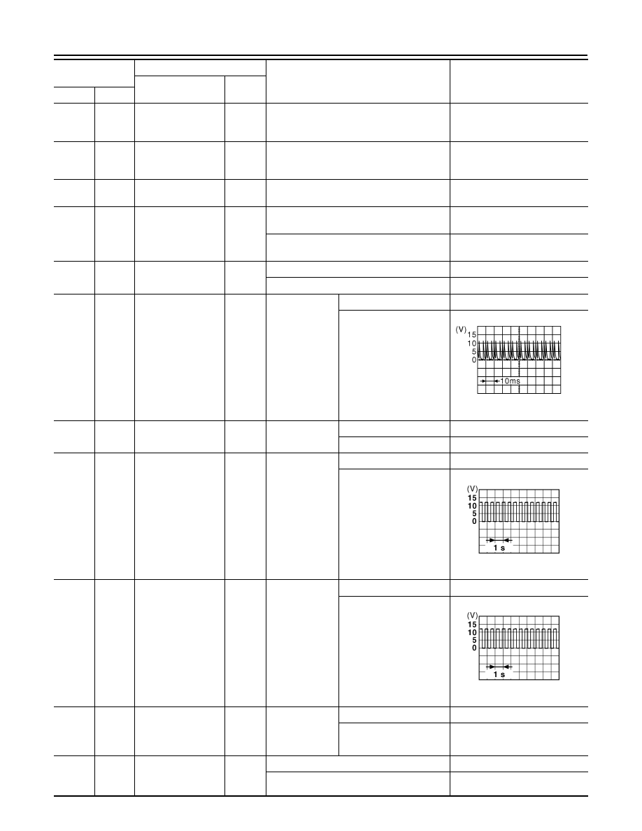
39
(P)
Ground
NATS antenna amp.
Input/
Output
Insert mechanical key into ignition key cylin-
der
Just after Insert mechanical key
into ignition key cylinder. Pointer
of tester should move
40
(LG)
Ground
NATS antenna amp.
Input/
Output
Insert mechanical key into ignition key cylin-
der
Just after Insert mechanical key
into ignition key cylinder. Pointer
of tester should move
41
(V)
Ground
Battery power sup-
ply
Input
Ignition switch OFF
Battery voltage
42
(V)
Ground
Interior room lamp
power supply
Output
After passing the interior room lamp battery
saver operation time
0 V
Any other time after passing the interior room
lamp battery saver operation time
Battery voltage
43
(L)
Ground
Rear wiper motor
Output
Rear wiper switch OFF
0 V
Rear wiper switch ON
Battery voltage
44
(L/W)
Ground
Rear wiper auto stop
Output
Ignition switch
ON
Rear wiper stop position
0 V
Any position other than
rear wiper stop position
45
(GR)
Ground
Back door lock actu-
ator
Output
Back door
opener switch
Pressed
Battery voltage (300ms)
Not pressed
0 V
47
(G/Y)
Ground
Turn signal LH
Output
Ignition switch
ON
Turn signal switch OFF
0 V
Turn signal switch LH
6.5 V
48
(G/B)
Ground
Turn signal RH
Output
Ignition switch
ON
Turn signal switch OFF
0 V
Turn signal switch RH
6.5 V
49
(Y)
Ground
Rear fog lamp
Output
Lighting switch
1ST and front
fog lamp switch
ON
Rear fog lamp switch OFF
0 V
Rear fog lamp switch ON
Battery voltage
51
(R/W)
*1
(R)
*2
Ground
Stop lamp switch
Output
Depress the brake pedal
Battery voltage
Release the brake pedal
0 V
Terminal No.
(Wire color)
Description
Condition
Value
(Approx.)
Signal name
Input/
Output
+
−
JPMIA0197GB
PKID0926E
PKID0926E

WCS
BCM (BODY CONTROL MODULE)
WCS-57
< ECU DIAGNOSIS >
C
D
E
F
G
H
I
J
K
L
M
B
A
O
P
*1: With Intelligent Key system
*2: Without Intelligent Key system
52
(R)
Ground
Room lamp timer
control
Output
Interior room
lamp
OFF
Battery voltage
ON
0 V
53
(L)
Ground
Power window pow-
er supply
Output
Ignition switch
OFF or ACC
0 V
ON
Battery voltage
54
(O)
Ground
Door unlock (All)
Output
Door lock/un-
lock switch
Pressed to the unlock side
Battery voltage
Pressed to the lock side
0 V
55
(B)
Ground
Ground
—
Ignition switch ON
0 V
56
(Y)
*1
(SB)
*2
Ground
Door lock (All)
Output
Door lock/un-
lock switch
Pressed to the unlock side
0 V
Pressed to the lock side
Battery voltage
57
(Y)
Ground
Battery power sup-
ply
Output
Ignition switch OFF
Battery voltage
58
(P)
Ground
Power window pow-
er supply
Output
Ignition switch OFF
Battery voltage
59
(BR)
Ground
Super lock
Output
When lock button of key fob or Intelligent Key
is not pressed
0 V
When lock button of key fob or Intelligent Key
is pressed
Battery voltage
60
(GR)
Ground
Driver door unlock
Output
Door lock/un-
lock switch
Pressed to the unlock side
Battery voltage
Pressed to the lock side
0 V
Terminal No.
(Wire color)
Description
Condition
Value
(Approx.)
Signal name
Input/
Output
+
−
Нет комментариевНе стесняйтесь поделиться с нами вашим ценным мнением.
Текст