Nissan Qashqai (2007-2010). Manual — part 1883
PG-70
< COMPONENT DIAGNOSIS >
[POWER SUPPLY & GROUND CIRCUIT]
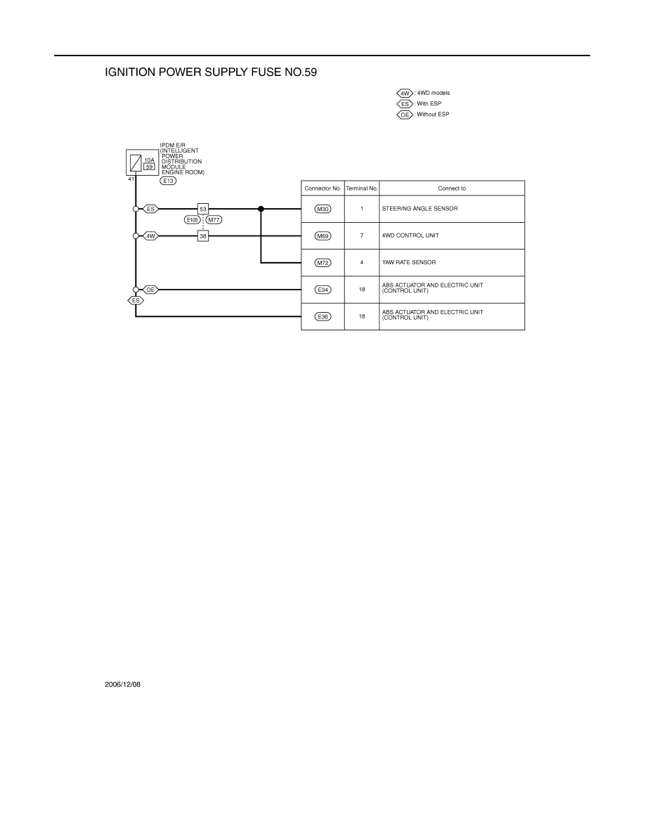
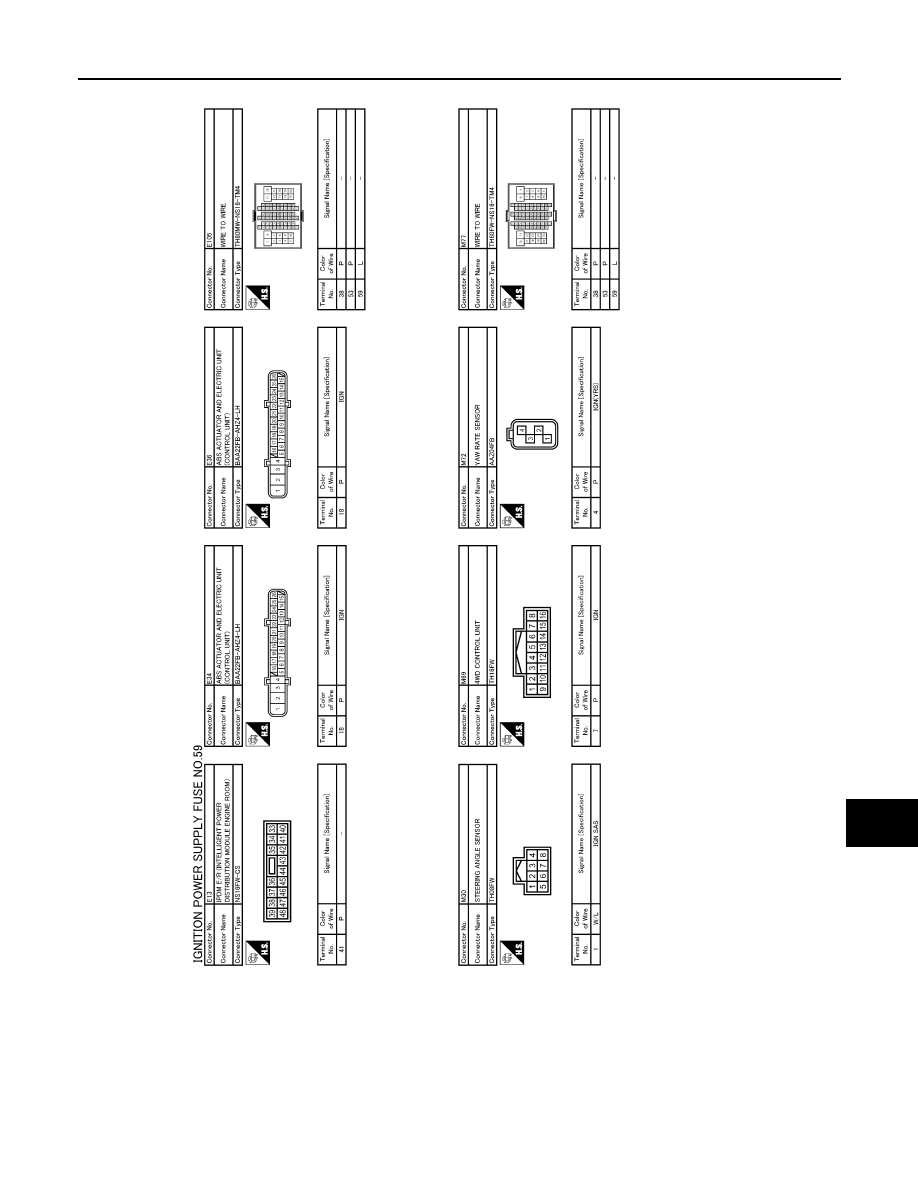
POWER SUPPLY ROUTING CIRCUIT
JCMWA0490GB
PG
POWER SUPPLY ROUTING CIRCUIT
PG-71
< COMPONENT DIAGNOSIS >
[POWER SUPPLY & GROUND CIRCUIT]
C
D
E
F
G
H
I
J
K
L
B
A
O
P
N
Fuse
INFOID:0000000000956066
JCMWA0491GB
PG-72
< COMPONENT DIAGNOSIS >
[POWER SUPPLY & GROUND CIRCUIT]
POWER SUPPLY ROUTING CIRCUIT
• If fuse is blown, be sure to eliminate cause of malfunction before
installing new fuse.
• Use fuse of specified rating. Never use fuse of more than specified
rating.
• Do not partially install fuse; always insert it into fuse holder prop-
erly.
• Remove fuse for “ELECTRICAL PARTS (BAT)” if vehicle is not
used for a long period of time.
Fusible Link
INFOID:0000000000956067
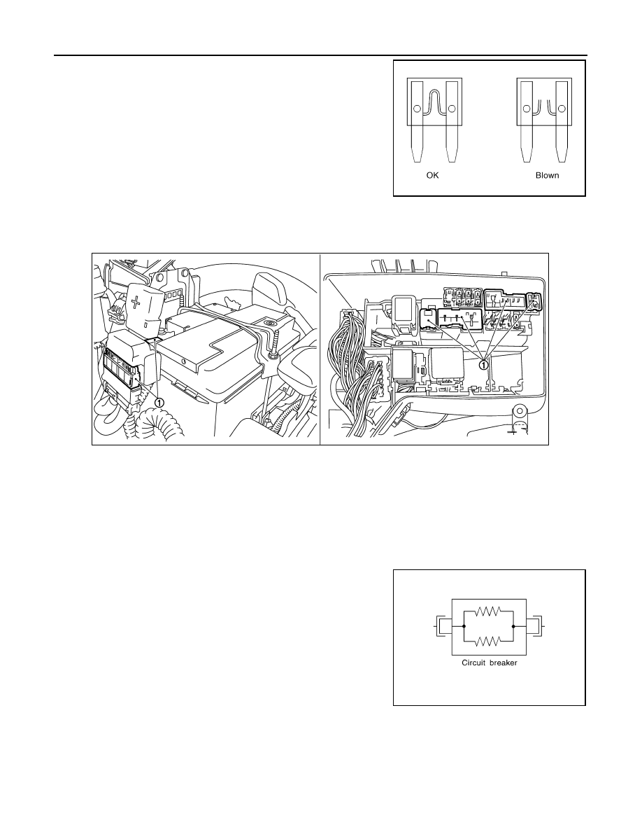
A melted fusible link can be detected either by visual inspection or by feeling with finger tip. If its condition is
questionable, use circuit tester or test lamp.
CAUTION:
• If fusible link should melt, it is possible that critical circuit (power supply or large current carrying
circuit) is shorted. In such a case, carefully check and eliminate cause of malfunction.
• Never wrap outside of fusible link with vinyl tape. Important: Never let fusible link touch any other
wiring harness, vinyl or rubber parts.
Circuit Breaker
INFOID:0000000000956068
The PTC thermistor generates heat in response to current flow. The
temperature (and resistance) of the thermistor element varies with
current flow. Excessive current flow will cause the element's temper-
ature to rise. When the temperature reaches a specified level, the
electrical resistance will rise sharply to control the circuit current.
Reduced current flow will cause the element to cool. Resistance falls
accordingly and normal circuit current flow is allowed to resume.
CEL083
1
: Fusible link
JPMIA0132ZZ
SEL109W
PG
HARNESS LAYOUT
PG-73
< COMPONENT DIAGNOSIS >
[POWER SUPPLY & GROUND CIRCUIT]
C
D
E
F
G
H
I
J
K
L
B
A
O
P
N
HARNESS LAYOUT
LHD
LHD : How To Read Harness Layout
INFOID:0000000000956069
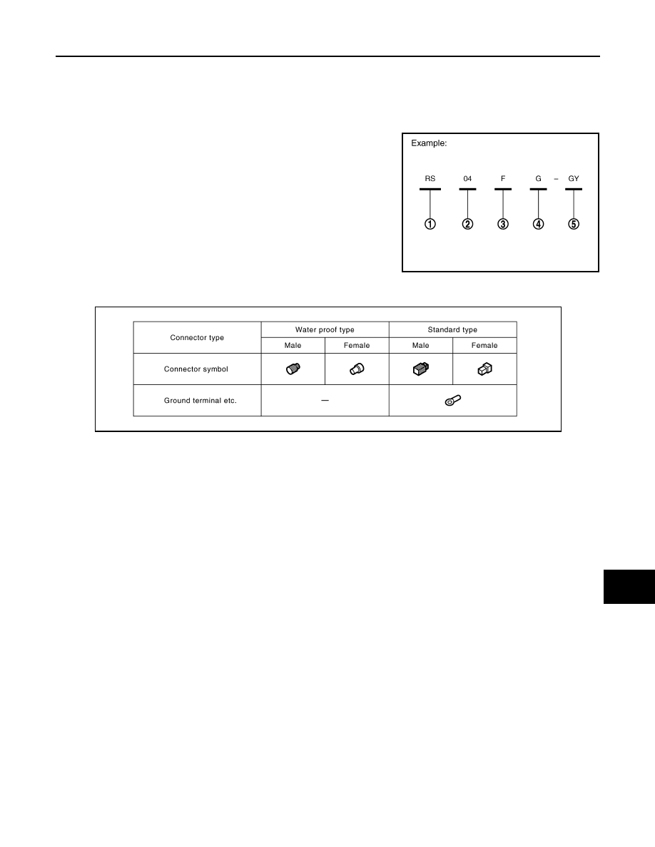
CONNECTOR SYMBOL
Main symbols of connector (in Harness Layout) are indicated in the below.
1
: Connector model
2
: Cavity
3
: Male (M) and female (F) terminals
4
: Connector color
5
: Special type
JPMIA0113GB
JPMIA0114GB
Нет комментариевНе стесняйтесь поделиться с нами вашим ценным мнением.
Текст