Nissan Qashqai (2007-2010). Manual — part 206

ECM
EC-343
< ECU DIAGNOSIS >
[HR16DE (WITH EURO-OBD)]
C
D
E
F
G
H
I
J
K
L
M
A
EC
N
P
O
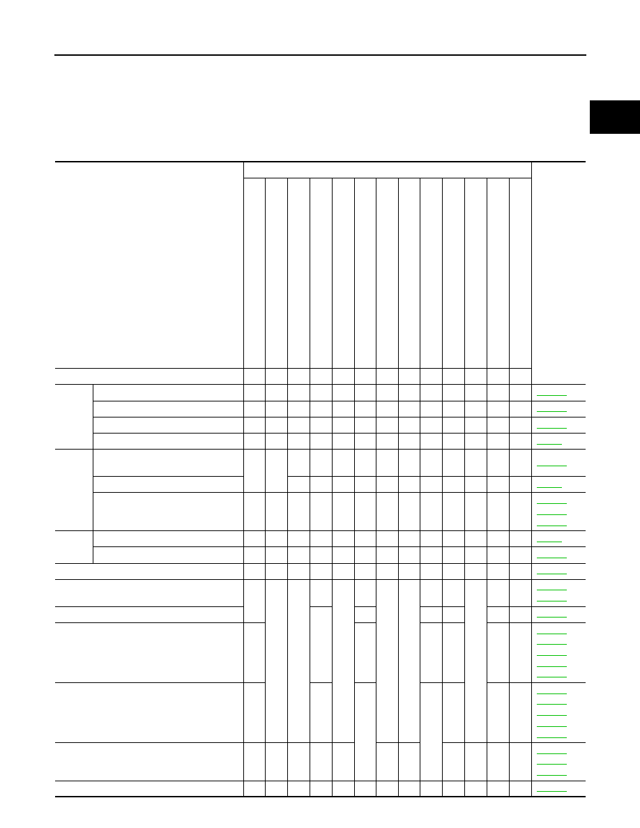
DRIVING PATTERN
• The time required for each diagnosis varies with road surface conditions, weather, altitude, individual driving
habits, etc.
Zone A refers to the range where the time, required for the diagnosis under normal conditions*, is the short-
est.
Zone B refers to the range where the diagnosis can still be performed if the diagnosis is not completed within
zone A.
*: Normal conditions refer to the following:
PBIB2451E

EC-344
< ECU DIAGNOSIS >
[HR16DE (WITH EURO-OBD)]
ECM
• Sea level
• Flat road
• Ambient air temperature: 20 - 30
°
C (68 - 86
°
F)
• Diagnosis is performed as quickly as possible under normal conditions.
Under different conditions [For example: ambient air temperature other than 20 - 30
°
C (68 - 86
°
F)], diagno-
sis may also be performed.
Pattern 1:
• The engine is started at the engine coolant temperature of
−
10 to 35
°
C (14 to 95
°
F)
(where the voltage between the ECM terminal 38 and ground is 3.0 - 4.3V).
• The engine must be operated at idle speed until the engine coolant temperature is greater than 70
°
C
(158
°
F) (where the voltage between the ECM terminal 38 and ground is lower than 1.4V).
Pattern 2:
• When steady-state driving is performed again even after it is interrupted, each diagnosis can be conducted.
In this case, the time required for diagnosis may be extended.
*1: Depress the accelerator pedal until vehicle speed is 90 km/h (56 MPH), then release the accelerator pedal
and keep it released for more than 10 seconds. Depress the accelerator pedal until vehicle speed is 90 km/h
(56 MPH) again.
*2: Checking the vehicle speed with GST is advised.
Test Value and Test Limit
INFOID:0000000001056535
The following is the information specified in Service $06 of ISO 15031-5.
The test value is a parameter used to determine whether a system/circuit diagnostic test is OK or NG while
being monitored by the ECM during self-diagnosis. The test limit is a reference value which is specified as the
maximum or minimum value and is compared with the test value being monitored.
These data (test value and test limit) are specified by Test ID (TID) and Component ID (CID) and can be dis-
played on the GST screen.
Item
Self-diagnostic test item
DTC
Test value
(GST display)
Test limit
TID
CID
CATALYST
Three way catalyst function
P0420
01H
81H
Min.
P0420
02H
81H
Min.
HO2S
Heated oxygen sensor 1
P0133
09H
04H
Max.
P1143
0AH
84H
Min.
P1144
08H
04H
Max.
P0132
0CH
04H
Max.
P0134
0DH
04H
Max.
Heated oxygen sensor 2
P0139
19H
86H
Min.
P1147
1AH
86H
Min.
P1146
1BH
06H
Max.
P0138
1CH
06H
Max.
HO2S HEATER
Heated oxygen sensor 1 heater
P0135
29H
08H
Max.
2AH
88H
Min.
Heated oxygen sensor 2 heater
P0141
2DH
0AH
Max.
2EH
8AH
Min.
ENGINE CONTROL SYSTEM SYMPTOMS
EC-345
< SYMPTOM DIAGNOSIS >
[HR16DE (WITH EURO-OBD)]
C
D
E
F
G
H
I
J
K
L
M
A
EC
N
P
O
SYMPTOM DIAGNOSIS
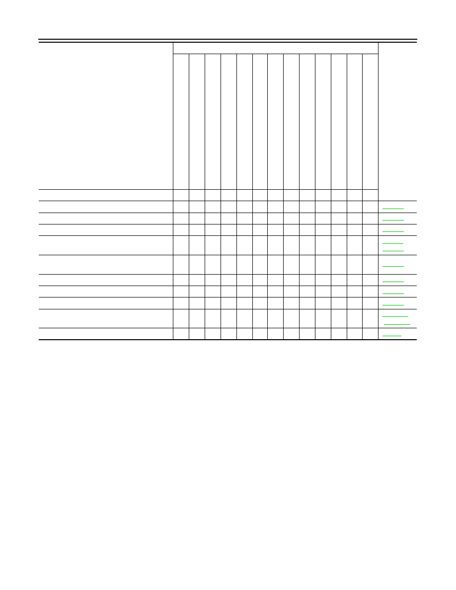
ENGINE CONTROL SYSTEM SYMPTOMS
Symptom Table
INFOID:0000000001056536
SYSTEM — BASIC ENGINE CONTROL SYSTEM
SYMPTOM
Reference
page
HARD/NO ST
AR
T
/REST
AR
T
(EXCP
.
H
A
)
ENGINE ST
ALL
HESIT
A
TION/SURGING/FLA
T
SPOT
SP
ARK KNOCK/DET
O
NA
TION
LACK
OF POWER/
POOR
ACC
E
LERA
TION
HIGH IDL
E
/LOW
IDLE
ROUG
H IDLE/HUNTING
IDLI
NG VIBRA
T
ION
SLOW/NO RETURN T
O
IDLE
OVERHEA
T
S/W
A
TER TEMPERA
T
UR
E
HIGH
EXCESS
IVE F
U
E
L
CONSUMP
T
IO
N
EXCESS
IVE OIL CONSUMP
T
ION
BA
TTER
Y
DEAD (UNDER CHARGE)
Warranty symptom code
AA
AB
AC
AD
AE
AF
AG
AH
AJ
AK
AL
AM
HA
Fuel
Fuel pump circuit
1
1
2
3
2
2
2
3
2
Fuel pressure regulator system
3
3
4
4
4
4
4
4
4
4
Fuel injector circuit
1
1
2
3
2
2
2
2
Evaporative emission system
3
3
4
4
4
4
4
4
4
4
Air
Positive crankcase ventilation sys-
tem
3
3
4
4
4
4
4
4
4
4
1
Incorrect idle speed adjustment
1
1
1
1
1
Electric throttle control actuator
1
1
2
3
3
2
2
2
2
2
2
,
,
Ignition
Incorrect ignition timing adjustment
3
3
1
1
1
1
1
1
Ignition circuit
1
1
2
2
2
2
2
2
Main power supply and ground circuit
2
2
3
3
3
3
3
2
3
Mass air flow sensor circuit
1
1
2
2
2
2
2
2
,
Engine coolant temperature sensor circuit
3
3
3
Heated oxygen sensor 1 circuit
,
,
,
,
Throttle position sensor circuit
2
2
,
,
,
,
Accelerator pedal position sensor circuit
3
2
1
,
,
Knock sensor circuit
2
3
EC-346
< SYMPTOM DIAGNOSIS >
[HR16DE (WITH EURO-OBD)]
ENGINE CONTROL SYSTEM SYMPTOMS
1 - 6: The numbers refer to the order of inspection.
(continued on next page)
SYSTEM — ENGINE MECHANICAL & OTHER
Crankshaft position sensor (POS) circuit
2
2
Camshaft position sensor (PHASE) circuit
3
2
Vehicle speed signal circuit
2
3
3
3
ECM
2
2
3
3
3
3
3
3
3
3
3
,
Intake valve timing control solenoid valve cir-
cuit
3
2
1
3
2
2
3
3
PNP switch circuit
3
3
3
3
3
Refrigerant pressure sensor circuit
2
3
3
4
Electrical load signal circuit
3
Air conditioner circuit
2
2
3
3
3
3
3
3
3
3
2
ABS actuator and electric unit (control unit)
4
SYMPTOM
Reference
page
HARD/NO S
T
A
R
T/RES
T
A
R
T (E
XCP
. HA)
E
N
GINE
ST
ALL
HES
IT
A
TION/SURGING/FLA
T
SPOT
S
P
ARK KNOC
K
/DET
O
NA
TI
ON
LACK OF
POWER/POOR ACCELERA
TION
HIG
H
IDL
E
/L
OW
ID
LE
ROUGH IDLE/HUNTING
ID
LING VI
BRA
T
ION
S
L
OW/NO RETU
RN
T
O
ID
LE
OVERHEA
T
S
/W
A
TER TEMPERA
T
URE HIG
H
E
X
CESSIVE
FUEL CON
S
UMP
T
ION
E
X
CESSIVE
OIL
C
O
NSUMP
T
ION
B
A
TTER
Y
DEAD (UNDER CHARGE)
Warranty symptom code
AA
AB
AC
AD
AE
AF
AG
AH
AJ
AK
AL
AM
HA
Нет комментариевНе стесняйтесь поделиться с нами вашим ценным мнением.
Текст