Nissan Qashqai (2007-2010). Manual — part 55
EM-168
< ON-VEHICLE REPAIR >
[MR20DE]
TIMING CHAIN
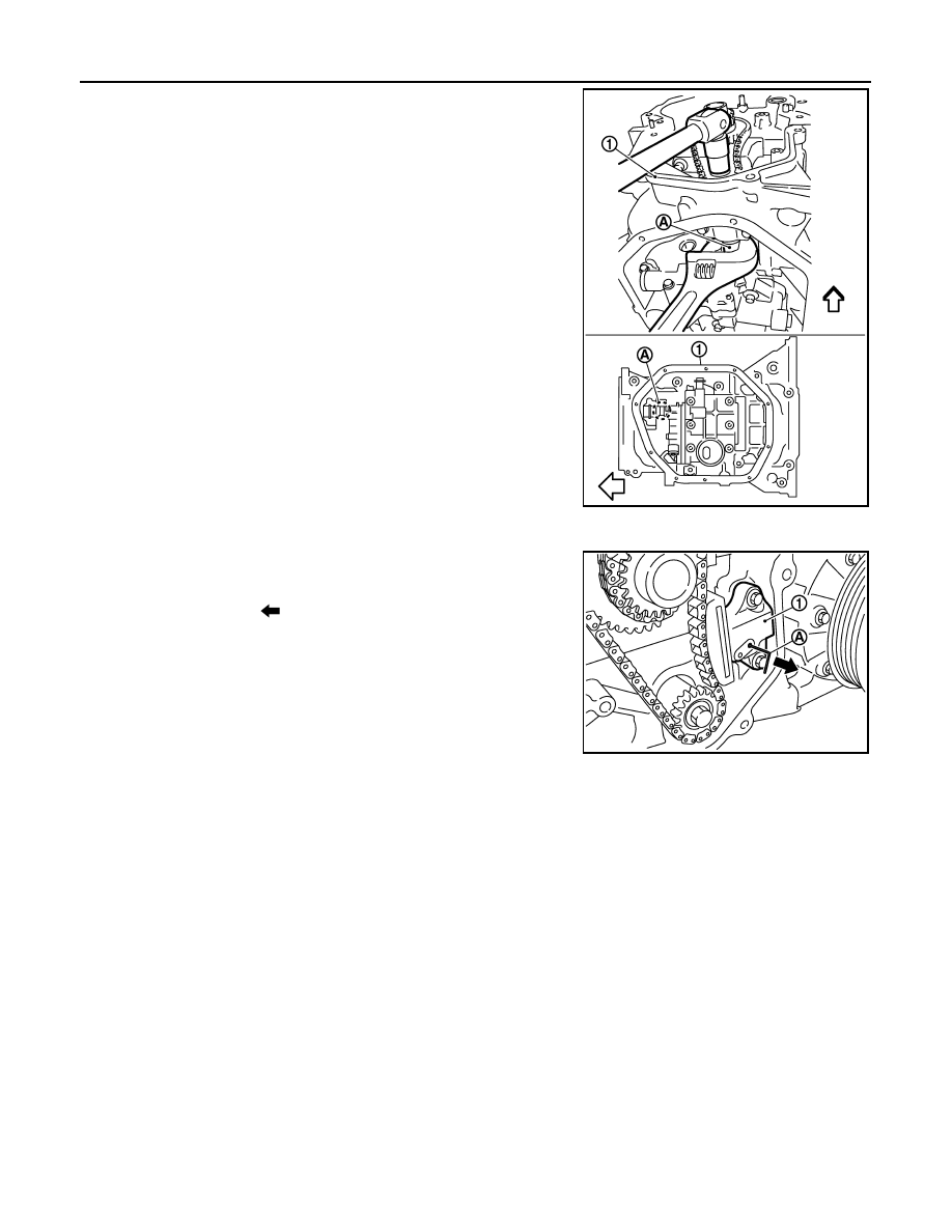
4.
Hold the WAF part of balancer unit shaft [WAF: 19.0 mm (0.75
in)] (A), and then tighten the balancer shaft sprocket bolt.
CAUTION:
• Secure the balancer unit shaft with the WAF part.
• Never loosen the balancer shaft sprocket bolt by tighten-
ing the balancer unit timing chain.
5.
Install balancer unit timing chain tensioner (1).
• Fix the plunger at the most compressed position using a stop-
per pin (A), and then install it.
• Securely pull out (
) the stopper pin after installing the bal-
ancer unit timing chain tensioner.
• Check matching mark position of balancer unit timing chain
and each sprocket again.
1
: Oil pan (upper)
: Engine front
PBIC3168J
PBIC3456J
TIMING CHAIN
EM-169
< ON-VEHICLE REPAIR >
[MR20DE]
C
D
E
F
G
H
I
J
K
L
M
A
EM
N
P
O
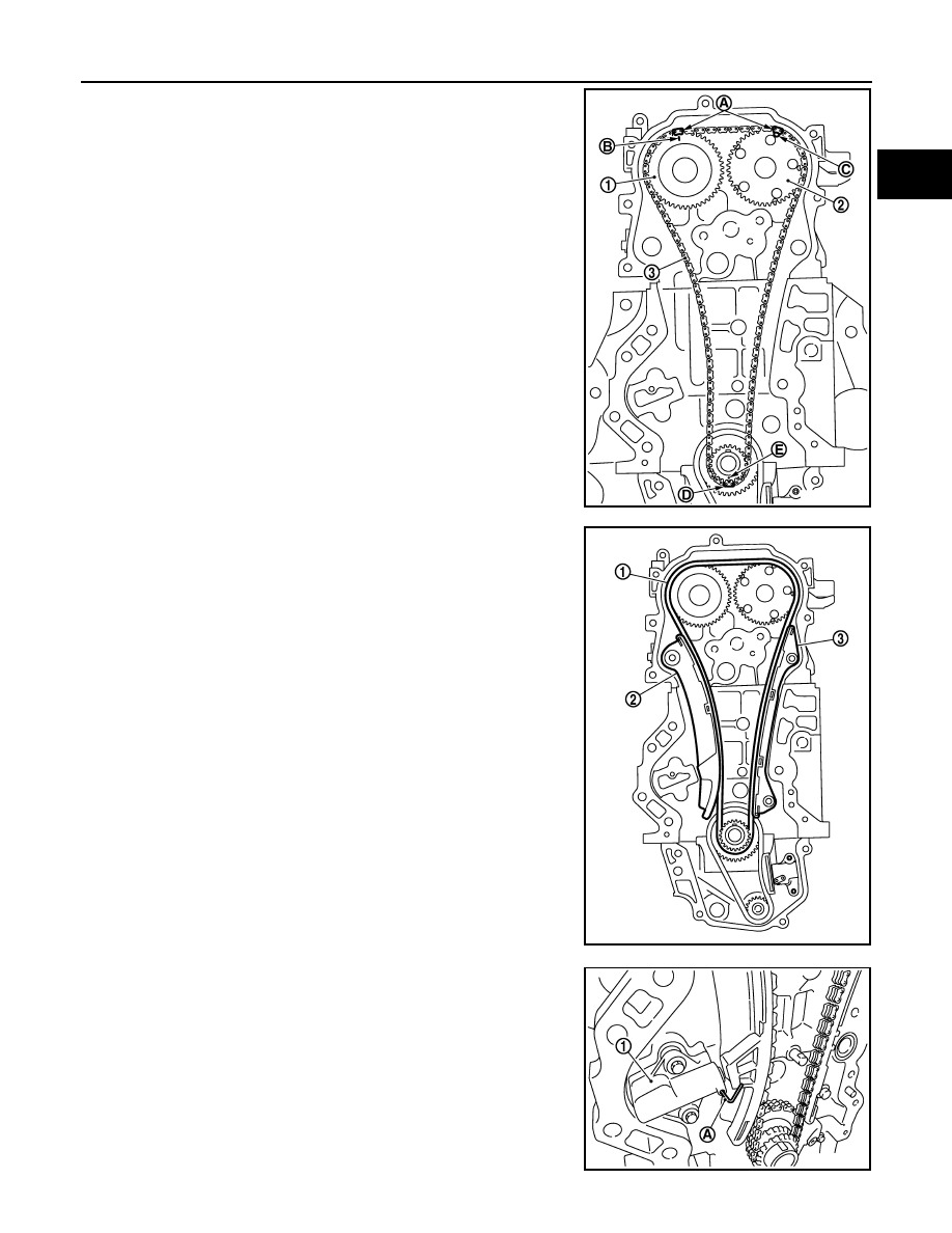
6.
Align the matching marks of each sprocket with the matching
marks of timing chain.
*: There are 2 outer grooves in camshaft sprocket (INT). The wider one is a
matching mark.
• If these matching marks are not aligned, rotate the camshaft
slightly by holding the hexagonal portion to correct the posi-
tion.
CAUTION:
Check matching mark position of each sprocket and timing
chain again after installing the timing chain.
7.
Install the timing chain tension guide (3) and the timing chain
slack guide (2).
8.
Install timing chain tensioner (1).
• Fix the plunger at the most compressed position using a stop-
per pin (A), and then install it.
• Securely pull out the stopper pin after installing the timing
chain tensioner.
1
: Camshaft sprocket (EXH)
2
: Camshaft sprocket (INT)
3
: Timing chain
A
: Matching mark (dark blue link)
B
: Matching mark (stamping)
C
: Matching mark (outer groove*)
D
: Matching mark (orange link)
E
: Matching mark (stamping)
PBIC3172J
1
: Timing chain
PBIC3166J
PBIC3165J
EM-170
< ON-VEHICLE REPAIR >
[MR20DE]
TIMING CHAIN
9.
Check matching mark position of timing chain and each sprocket again.
10. Install front oil seal. Refer to
EM-182, "FRONT OIL SEAL : Removal and Installation"
11. Install front cover with the following procedure:
a.
Install new O-ring to cylinder block.
CAUTION:
Never misalign O-ring.
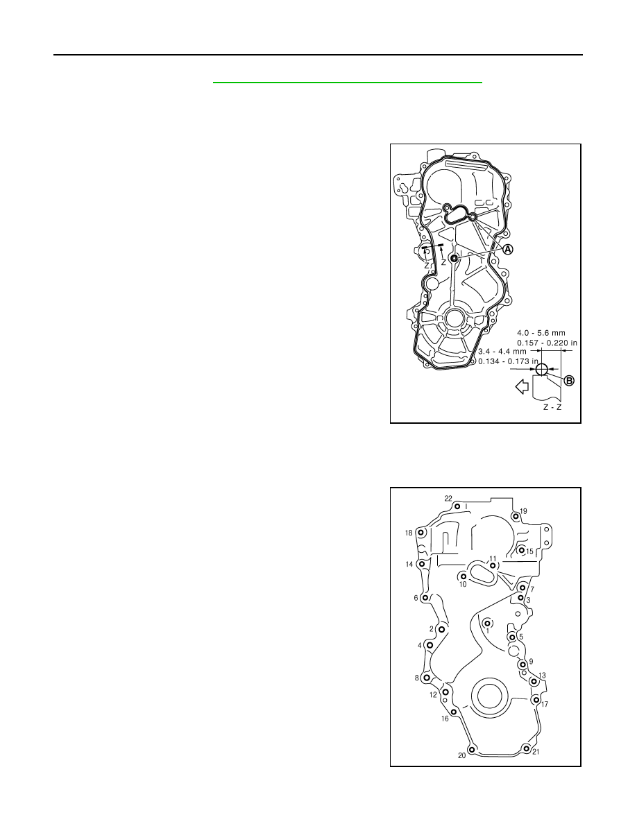
b.
Apply a continuous bead of liquid gasket (B) with a tube presser
(commercial service tool) to front cover as shown in the figure.
Use Genuine Liquid Gasket or equivalent.
c.
Make sure that matching marks of timing chain and each sprocket are still aligned. Then install front cover.
CAUTION:
• Make sure O-ring on cylinder block is correctly installed.
• Be careful not to damage front oil seal by interference with front end of crankshaft.
d.
Install front cover, and tighten mounting bolts in numerical order
as shown in the figure.
• Refer to the following for the installation position of bolts.
CAUTION:
Attaching should be done within 5 minutes after liquid gas-
ket application.
e.
After all bolts are tightened, retighten them to specified torque in
numerical order as shown in the figure.
CAUTION:
Be sure to wipe off any excessive liquid gasket leaking.
12. Install crankshaft pulley with the following procedure:
A
: Liquid gasket application area
: Engine outside
JPBIA0291ZZ
M6
: No.1
M10
: No. 6, 7, 10, 11, 14
M12
: No. 2, 4, 8, 12
M8
: Except the above
PBIC3164J
TIMING CHAIN
EM-171
< ON-VEHICLE REPAIR >
[MR20DE]
C
D
E
F
G
H
I
J
K
L
M
A
EM
N
P
O
a.
When inserting crankshaft pulley with a plastic hammer, tap on its center portion (not circumference).
CAUTION:
Never damage front oil seal lip section.
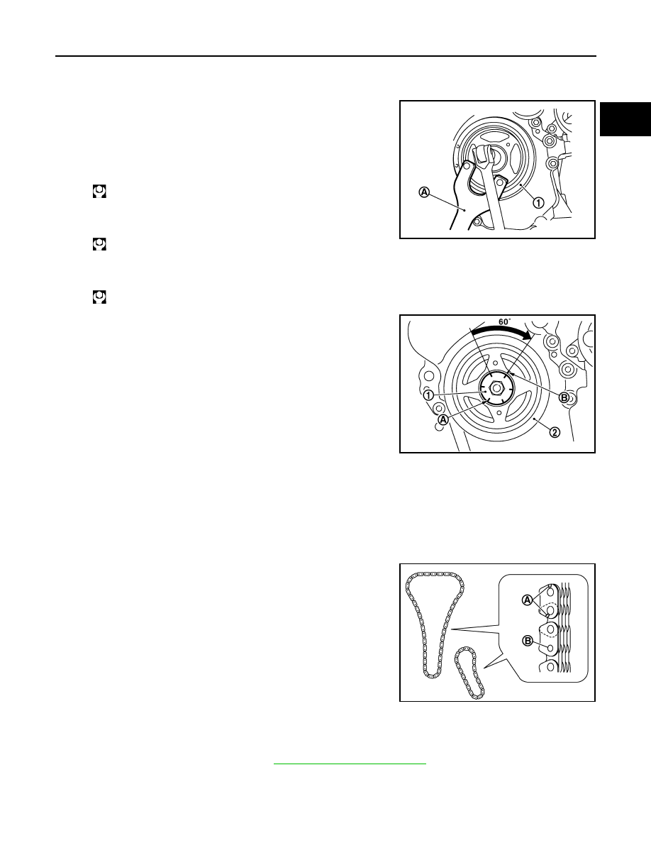
b.
Secure crankshaft pulley (1) with a pulley holder (A) (commer-
cial service tool).
c.
Apply new engine oil to thread and seat surfaces of crankshaft
pulley bolt.
d.
Tighten crankshaft pulley bolt.
e.
Completely loosen.
f.
Tighten crankshaft pulley bolt.
g.
Put a paint mark (B) on crankshaft pulley (2), matching with any
one of six easy to recognize angle marks (A) on crankshaft pul-
ley bolt (1) flange.
h.
Turn another 60 degrees clockwise (angle tightening).
• Check the tightening angle with movement of one angle mark.
i.
Make sure that crankshaft rotates clockwise smoothly.
13. Install remaining parts in the reverse order of removal.
Inspection
INFOID:0000000000893949
INSPECTION AFTER REMOVAL
Timing Chain
Check for cracks (A) and any excessive wear (B) at link plates and
roller links of timing chain. Replace timing chain as necessary.
INSPECTION AFTER INSTALLATION
Inspection for Leaks
• Before starting engine, check oil/fluid levels including engine coolant and engine oil. If less than required
quantity, fill to the specified level. Refer to
MA-21, "Fluids and Lubricants"
.
• Use procedure below to check for fuel leakage.
- Turn ignition switch “ON” (with engine stopped). With fuel pressure applied to fuel piping, check for fuel leak-
age at connection points.
: 68.6 N·m (7.0 kg-m, 51 ft-lb)
: 0 N·m (0 kg-m, 0 ft-lb)
: 29.4 N·m (3.0 kg-m, 22 ft-lb)
PBIC3961E
PBIC3963E
PBIC3169J
Нет комментариевНе стесняйтесь поделиться с нами вашим ценным мнением.
Текст