Nissan Qashqai (2007-2010). Manual — part 61
EM-192
< ON-VEHICLE REPAIR >
[MR20DE]
CYLINDER HEAD
• If the calculated value exceeds the limit, replace valve and/or valve guide. When valve guide must be
EM-187, "Disassembly and Assembly"
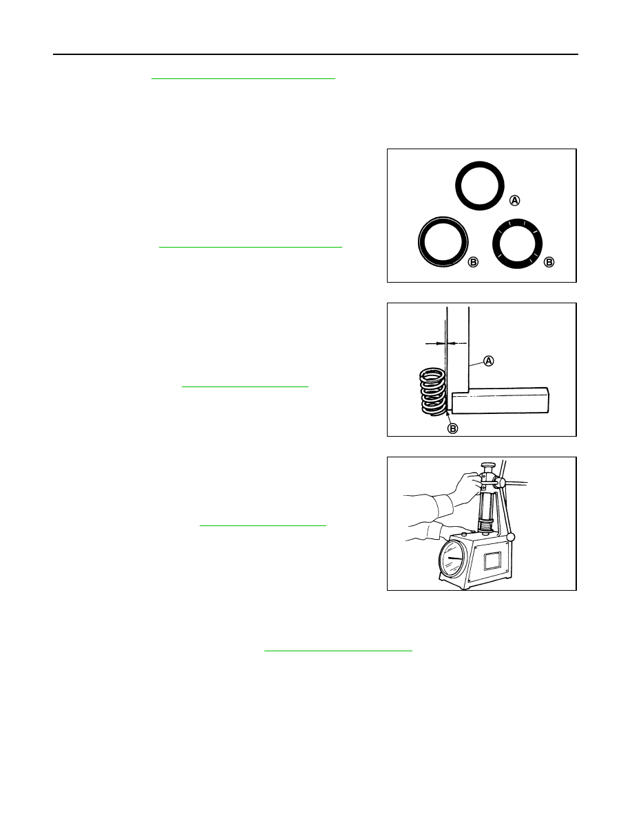
VALVE SEAT CONTACT
• After confirming that the dimensions of valve guides and valves are within the specifications, perform this
procedure.
• Apply prussian blue (or white lead) onto contacting surface of valve seat to check the condition of the valve
contact on the surface.
• Check if the contact area band is continuous all around the circum-
ference.
• If not, grind to adjust valve fitting and check again. If the contacting
surface still has “NG” conditions even after the re-check, replace
valve seat. Refer to
EM-187, "Disassembly and Assembly"
.
VALVE SPRING SQUARENESS
• Set a try square (A) along the side of valve spring and rotate
spring. Measure the maximum clearance between the top of spring
and try square.
• If it exceeds the limit, replace valve spring.
VALVE SPRING DIMENSIONS AND VALVE SPRING PRESSURE LOAD
• Check valve spring pressure with valve spring seat installed at the
specified spring height.
CAUTION:
Never remove valve spring seat from valve spring.
• If the installation load or load with valve open is out of the stan-
dard, replace valve spring (with valve spring seat).
INSPECTION AFTER INSTALLATION
Inspection for Leaks
• Before starting engine, check oil/fluid levels including engine coolant and engine oil. If less than required
quantity, fill to the specified level. Refer to
MA-21, "Fluids and Lubricants"
.
• Use procedure below to check for fuel leakage.
- Turn ignition switch “ON” (with engine stopped). With fuel pressure applied to fuel piping, check for fuel leak-
age at connection points.
- Start engine. With engine speed increased, check again for fuel leakage at connection points.
• Run engine to check for unusual noise and vibration.
• Warm up engine thoroughly to make sure there is no leakage of fuel, exhaust gases, or any oil/fluids includ-
ing engine oil and engine coolant.
• Bleed air from lines and hoses of applicable lines, such as in cooling system.
• After cooling down engine, again check oil/fluid levels including engine oil and engine coolant. Refill to the
specified level, if necessary.
A
: OK
B
: NG
JPBIA0187ZZ
B
: Contact
Limit
: Refer to
PBIC3219J
Standard
: Refer to
SEM113
CYLINDER HEAD
EM-193
< ON-VEHICLE REPAIR >
[MR20DE]
C
D
E
F
G
H
I
J
K
L
M
A
EM
N
P
O
Summary of the inspection items:
* Transmission/transaxle/CVT fluid, power steering fluid, brake fluid, etc.
Item
Before starting engine
Engine running
After engine stopped
Engine coolant
Level
Leakage
Level
Engine oil
Level
Leakage
Level
Other oils and fluid*
Level
Leakage
Level
Fuel
Leakage
Leakage
Leakage
Exhaust gases
—
Leakage
—
EM-194
< REMOVAL AND INSTALLATION >
[MR20DE]
ENGINE ASSEMBLY
REMOVAL AND INSTALLATION
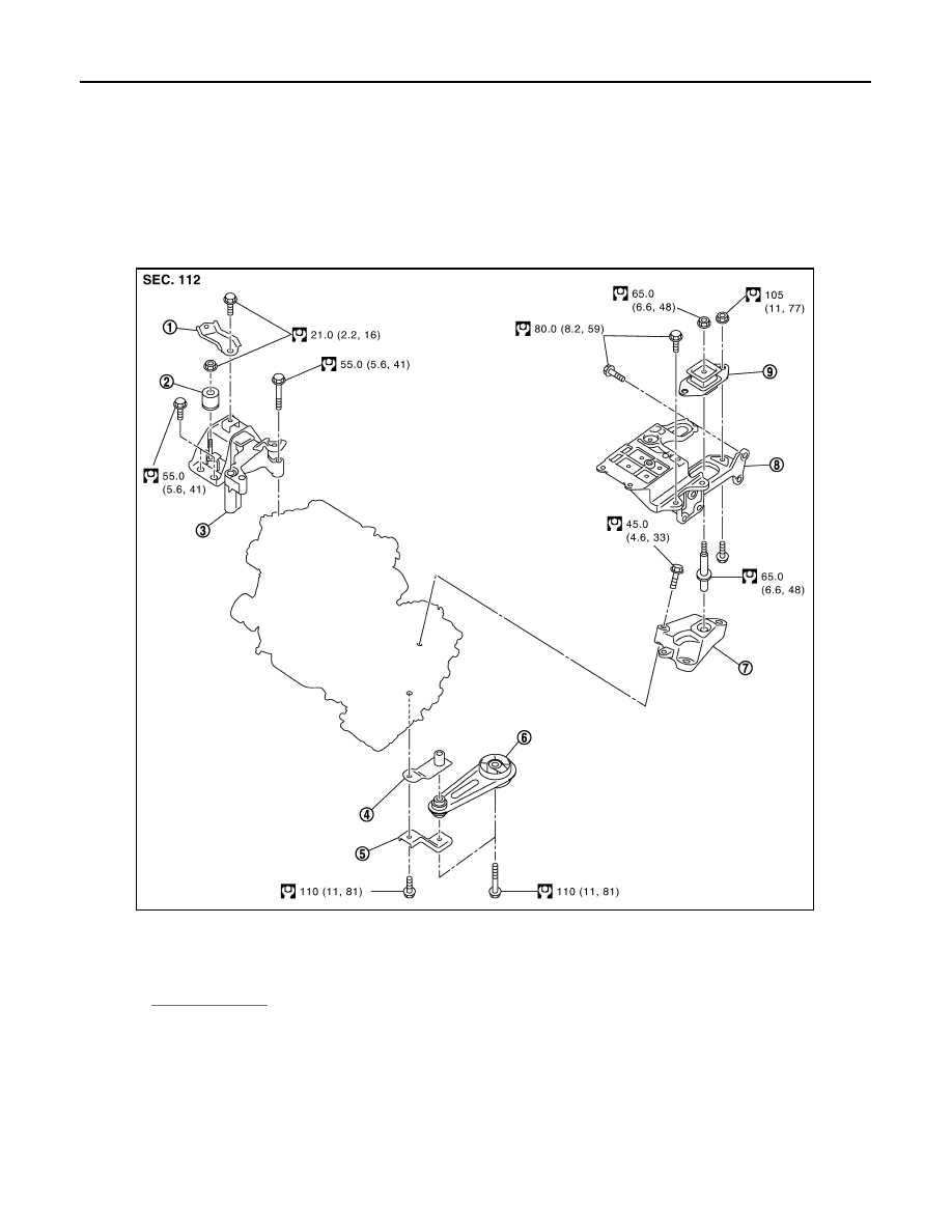
ENGINE ASSEMBLY
M/T
M/T : Exploded View
INFOID:0000000000893959
2WD models
4WD models
1.
Engine mounting stay
2.
Dynamic damper
3.
Engine mounting insulator (RH)
4.
Rear engine mounting bracket
5.
Rear engine mounting bracket
6.
Rear torque rod
7.
Engine mounting bracket (LH)
8.
Engine mounting bracket (LH)
9.
Engine mounting insulator (LH)
Refer to
for symbols in the figure.
JPBIA0392GB
ENGINE ASSEMBLY
EM-195
< REMOVAL AND INSTALLATION >
[MR20DE]
C
D
E
F
G
H
I
J
K
L
M
A
EM
N
P
O
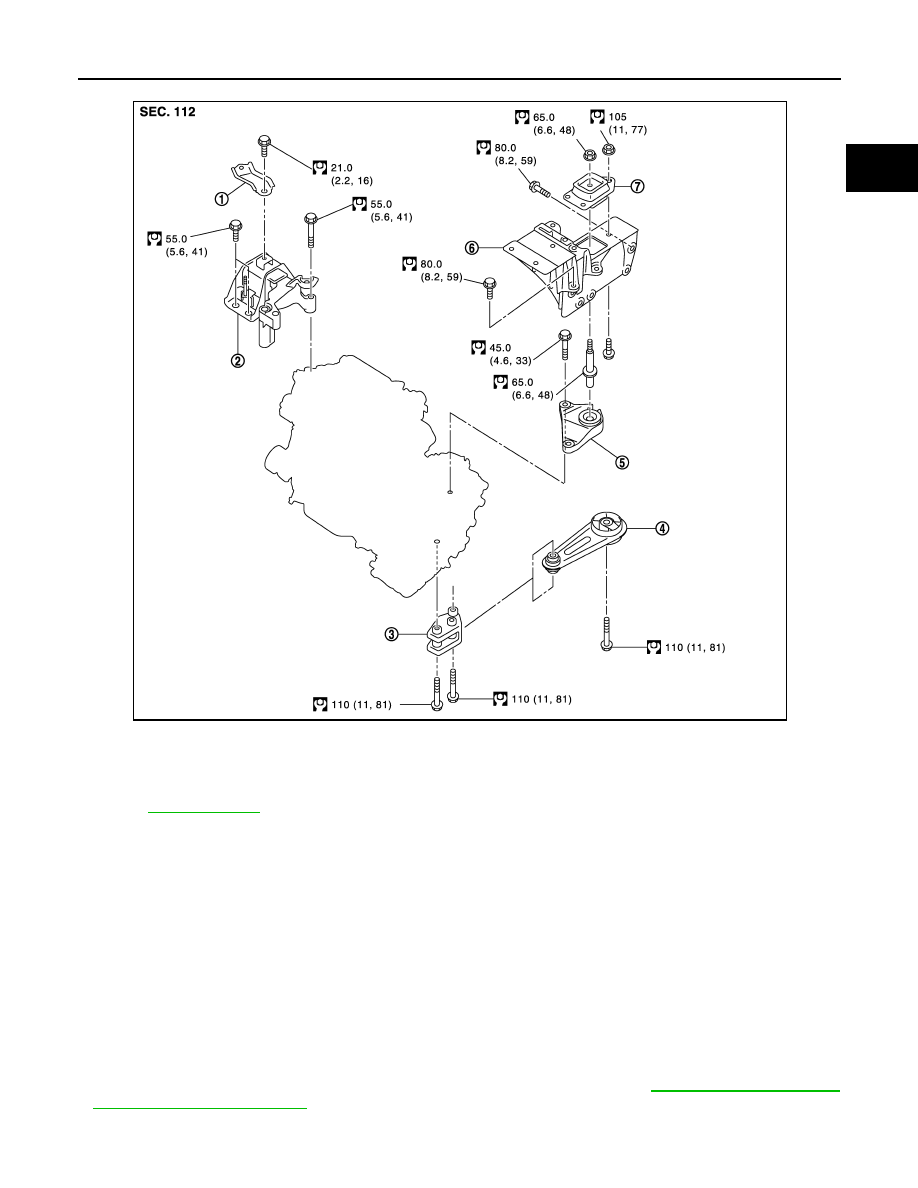
M/T : Removal and Installation
INFOID:0000000000893960
WARNING:
• Situate the vehicle on a flat and solid surface.
• Place chocks at front and back of rear wheels.
• Attach proper slingers and bolts described in PARTS CATALOG if engine slingers are not equipped.
CAUTION:
• Always be careful to work safely, avoid forceful or uninstructed operations.
• Never start working until exhaust system and coolant are cool enough.
• If items or work required are not covered by the engine section, refer to the applicable sections.
• Always use the support point specified for lifting.
• Use either 2-pole lift type or separate type lift as best you can. If board-on type is used for unavoid-
able reasons, support at the rear axle jacking point with a transmission jack or similar tool before
starting work, in preparation for the backward shift of center of gravity.
• For supporting points for lifting and jacking point at rear axle, refer to
REMOVAL
1.
Engine mounting stay
2.
Engine mounting insulator (RH)
3.
Rear engine mounting bracket
4.
Rear torque rod
5.
Engine mounting bracket (LH)
6.
Engine mounting bracket (LH)
7.
Engine mounting insulator (LH)
Refer to
for symbols in the figure.
JPBIA0393GB
Нет комментариевНе стесняйтесь поделиться с нами вашим ценным мнением.
Текст