Nissan Qashqai (2007-2010). Manual — part 467
P0606 ECM
EC-1387
< COMPONENT DIAGNOSIS >
[K9K]
C
D
E
F
G
H
I
J
K
L
M
A
EC
N
P
O
P0606 ECM
Description
INFOID:0000000000967577
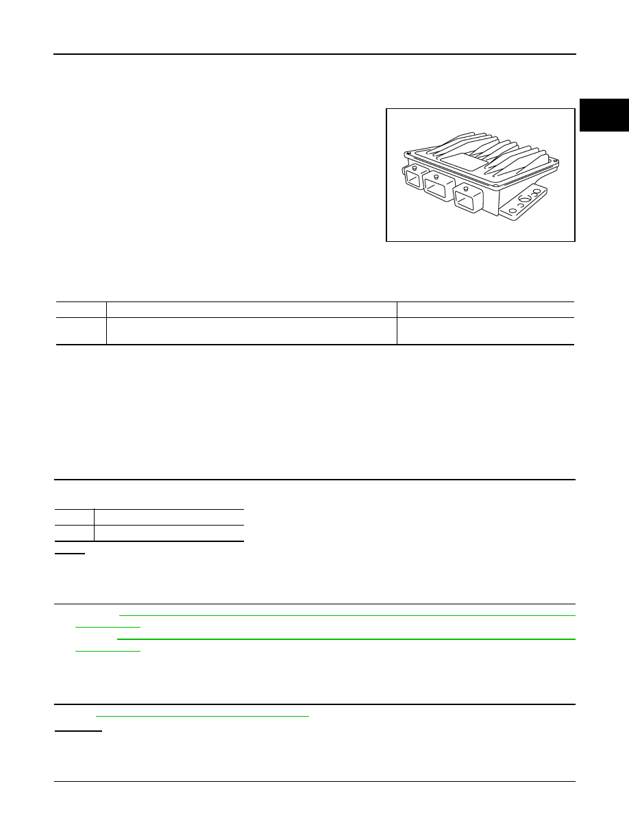
The ECM consists of a microcomputer and connectors for signal
input and output and for power supply. The ECM controls the engine.
DTC Logic
INFOID:0000000001115096
DTC DETECTION LOGIC
NOTE:
• If DTC P0606 is displayed with other DTC, first perform the trouble diagnosis for other DTC.
• Conditions for applying the diagnostic procedure to the stored DTCs:
The DTC is declared present after an attempted start, or with the engine running.
• If the DTC is present:
- Malfunction indicator (Red) lights up.
- Malfunction indicator (Yellow) lights up.
Diagnosis Procedure
INFOID:0000000000967579
1.
CHECK DTC
Make sure that which malfunction (DTC second line indication) is displayed.
A or B
A
>> GO TO 2.
B
>> GO TO 3.
2.
REPLACE ECM
1.
Perform
EC-1273, "ADDITIONAL SERVICE WHEN REPLACING CONTROL UNIT : Special Repair
.
2.
Perform
EC-1274, "EGR VOLUME CONTROL VALVE CLOSED POSITION LEARNING : Special Repair
.
>> INSPECTION END
3.
CHECK CAN COMMUNICATION LINE
LAN-59, "CAN Communication Signal Chart"
OK or NG
OK
>> GO TO 4.
NG
>> Repair or replace.
4.
CHECK DTC WITH ABS ACTUATOR AND ELECTRIC UNIT (CONTROL UNIT)
MBIB1517E
DTC No.
Trouble diagnosis name
Possible cause
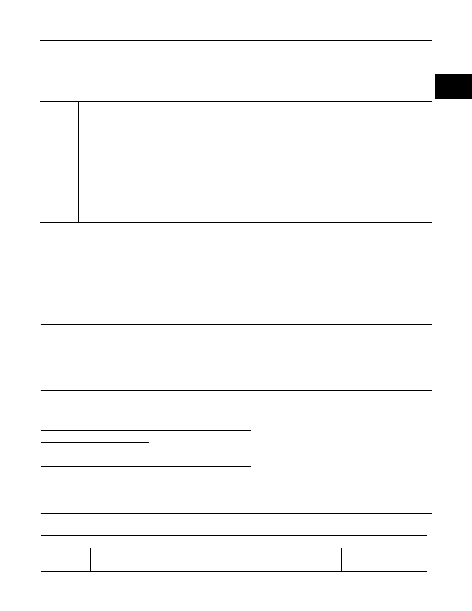
P0606
ECM
• 1.DEF to 20.DEF: Internal electric malfunction
• ECM
A
Except 9.DEFF
B
9.DEF

EC-1388
< COMPONENT DIAGNOSIS >
[K9K]
P0606 ECM
Refer to
BRC-17, "CONSULT-III Function (ABS)"
(without ESP) or
BRC-96, "CONSULT-III Function (ABS)"
(with ESP).
OK or NG
OK
>> GO TO 5.
NG
>> Repair or replace.
5.
REPLACE ECM
1.
Perform
EC-1273, "ADDITIONAL SERVICE WHEN REPLACING CONTROL UNIT : Special Repair
.
2.
Perform
EC-1274, "EGR VOLUME CONTROL VALVE CLOSED POSITION LEARNING : Special Repair
.
>> INSPECTION END
P0641 SENSOR POWER SUPPLY
EC-1389
< COMPONENT DIAGNOSIS >
[K9K]
C
D
E
F
G
H
I
J
K
L
M
A
EC
N
P
O
P0641 SENSOR POWER SUPPLY
DTC Logic
INFOID:0000000001115097
DTC DETECTION LOGIC
NOTE:
• If DTC P0641 is displayed with DTC P0100, P0101, P0110, P0190, P0225, P0409, P0530, P2120, first
perform trouble diagnosis for DTC P0641.
- Conditions for applying the diagnostic procedure to the stored DTCs:
The DTC is declared present after the ignition has been switched on.
- If the DTC is present:
- Malfunction indicator (Red) lights up.
Diagnosis Procedure
INFOID:0000000001098423
1.
CHECK GROUND CONNECTION
1.
Turn ignition switch OFF.
2.
Check ground connection E17. Refer to Ground Inspection in
.
Is the inspection result normal?
YES
>> GO TO 2.
NO
>> Repair or replace ground connection.
2.
CHECK ACCELERATOR PEDAL POSITION SENSOR 2 POWER SUPPLY CIRCUIT
1.
Disconnect accelerator pedal position (APP) sensor harness connector.
2.
Turn ignition switch ON.
3.
Check the voltage between APP sensor harness connector and ground.
Is the inspection result normal?
YES
>> GO TO 4.
NO
>> GO TO 3.
3.
CHECK SENSOR POWER SUPPLY CIRCUITS
Check harness for short to power and short to ground, between the following terminals.
DTC No.
Trouble diagnosis name
Possible cause
P0641
SENSOR POWER SUPPLY CIRCUIT
• 1.DEF: Signal outside lower level
• 2.DEF: Signal outside upper level
• Harness or connectors
(The APP sensor 2 power supply circuit is shorted.)
(Fuel rail pressure sensor circuit is shorted.)
(EGR volume control valve control position sensor circuit
is shorted.)
(Mass air flow sensor circuit is shorted.)
(Refrigerant pressure sensor circuit is shorted.)
• Accelerator pedal position sensor
(APP sensor 2)
• Fuel rail pressure sensor
• EGR volume control valve control position sensor
• Mass air flow sensor
• Refrigerant pressure sensor
APP sensor
Ground
Voltage
Connector
Terminal
E110
5
Ground
Approx. 5V
ECM
Sensor
Connector
Terminal
Name
Connector
Terminal
E60
118
APP sensor
E110
5

EC-1390
< COMPONENT DIAGNOSIS >
[K9K]
P0641 SENSOR POWER SUPPLY
Is the inspection result normal?
YES
>> GO TO 5.
NO
>> Repair short to ground or short to power in harness or connectors.
4.
CHECK SENSOR GROUND CIRCUITS
Check harness for short to power and short to ground, between the following terminals.
Is the inspection result normal?
YES
>> GO TO 5.
NO
>> Repair short to ground or short to power in harness or connectors.
5.
CHECK COMPONENTS
Check the following.
• Refrigerant pressure sensor (Refer to
EC-1380, "Diagnosis Procedure"
• EGR volume control valve (EGR volume control valve control position sensor) (Refer to
• Fuel rail pressure sensor (Refer to
EC-1350, "Component Inspection"
.)
• Mass air flow sensor (Refer to
EC-1337, "Component Inspection"
Is the inspection result normal?
YES
>> GO TO 6.
NO
>> Replace malfunctioning component.
6.
CHECK APP SENSOR
EC-1359, "Component Inspection"
.
Is the inspection result normal?
YES
>> GO TO 7.
NO
>> Replace APP sensor.
7.
CHECK INTERMITTENT INCIDENT
GI-39, "Intermittent Incident"
>> INSPECTION END
F68
89
Refrigerant pressure sensor
E50
3
85
EGR volume control valve (EGR volume control valve control posi-
tion sensor)
F99
1
F85
20
Fuel rail pressure sensor
F102
3
28
Mass air flow sensor
E15
5
ECM
Sensor
Connector
Terminal
Name
Connector
Terminal
ECM
Sensor
Connector
Terminal
Name
Connector
Terminal
E60
120
APP sensor
E110
1
F68
74
Refrigerant pressure sensor
E50
1
82
EGR volume control valve (EGR volume control valve control posi-
tion sensor)
F99
3
F85
15
Fuel rail pressure sensor
F102
2
30
Mass air flow sensor
E15
2
Нет комментариевНе стесняйтесь поделиться с нами вашим ценным мнением.
Текст