Nissan Qashqai (2007-2010). Manual — part 998
POWER SUPPLY AND GROUND CIRCUIT
DLK-71
< COMPONENT DIAGNOSIS >
[WITH I-KEY, WITHOUT SUPER LOCK]
C
D
E
F
G
H
I
J
L
M
A
B
DLK
N
O
P
POWER SUPPLY AND GROUND CIRCUIT
INTELLIGENT KEY UNIT
INTELLIGENT KEY UNIT : Diagnosis Procedure
INFOID:0000000000939085
1.
CHECK FUSE AND FUSIBLE LINK
Check that the following fuse is not blown.
Is the fuse blown?
YES
>> Replace the blown fuse after repairing the affected circuit if a fuse is blown.
NO
>> GO TO 2.
2.
CHECK POWER SUPPLY CIRCUIT
1.
Disconnect Intelligent Key unit connector.
2.
Turn ignition switch ON.
3.
Check voltage between Intelligent Key unit harness connector and ground.
Is the measurement value normal?
YES
>> GO TO 3.
NO
>> Repair harness or connector.
3.
CHECK GROUND CIRCUIT
Check continuity between Intelligent Key unit harness connector and ground.
Does continuity exist?
YES
>> Intelligent Key unit power supply and ground circuit are OK.
NO
>> Repair harness or connector.
BCM
BCM : Diagnosis Procedure
INFOID:0000000001034129
1.
CHECK FUSE AND FUSIBLE LINK
Check that the following fuse and fusible link are not blown.
Is the fuse fusing?
YES
>> Replace the blown fuse or fusible link after repairing the affected circuit if a fuse or fusible link is
blown.
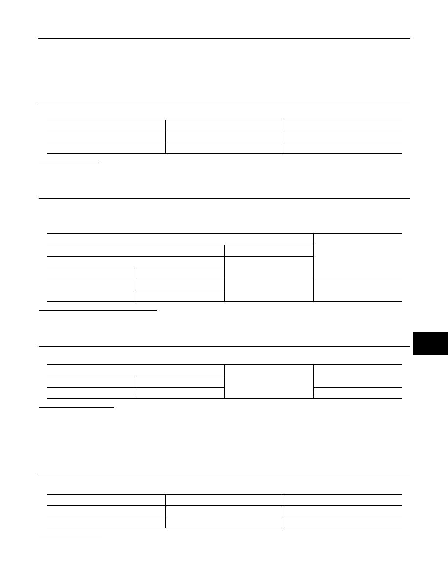
Terminal No.
Signal name
Fuse No.
11
Battery power supply
9 (10A)
6
Ignition power supply
4 (10A)
Terminal
Voltage (V)
(Approx.)
(+)
(
−
)
Intelligent Key unit
Ground
Connector
Terminal
M40
11
Battery voltage
6
Intelligent Key unit
Ground
Continuity
Connector
Terminal
M40
12
Exists
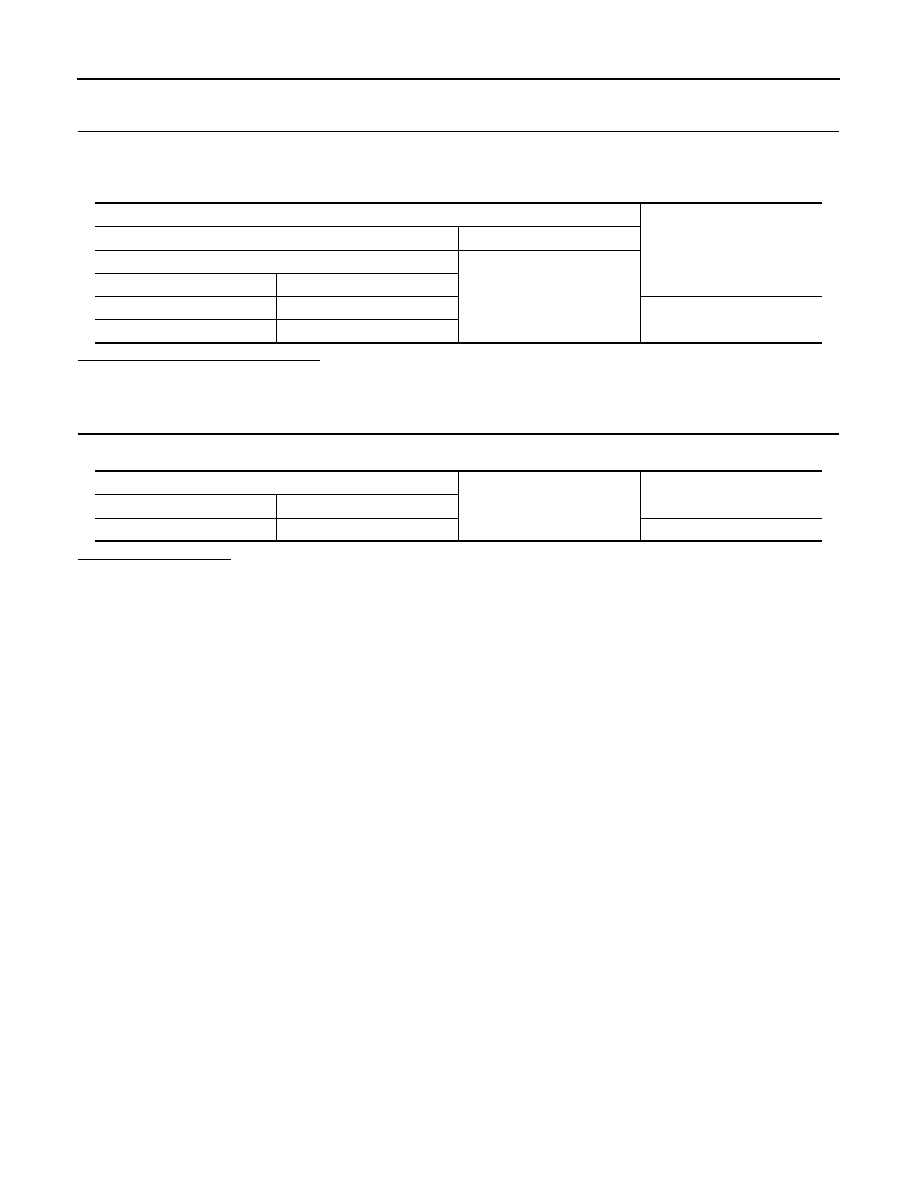
Terminal No.
Signal name
Fuse and fusible link No.
41
Battery power supply
9 (10A)
57
J (40A)
DLK-72
< COMPONENT DIAGNOSIS >
[WITH I-KEY, WITHOUT SUPER LOCK]
POWER SUPPLY AND GROUND CIRCUIT
NO
>> GO TO 2.
2.
CHECK POWER SUPPLY CIRCUIT
1.
Turn ignition switch OFF.
2.
Disconnect BCM connectors.
3.
Check voltage between BCM harness connector and ground.
Is the measurement value normal?
YES
>> GO TO 3.
NO
>> Repair harness or connector.
3.
CHECK GROUND CIRCUIT
Check continuity between BCM harness connector and ground.
Does continuity exist?
YES
>> BCM power supply and ground circuit are OK.
NO
>> Repair harness or connector.
Terminals
Voltage
(Approx.)
(+)
(
−
)
BCM
Ground
Connector
Terminal
M66
41
Battery voltage
M67
57
BCM
Ground
Continuity
Connector
Terminal
M67
55
Existed
DOOR LOCK AND UNLOCK SWITCH
DLK-73
< COMPONENT DIAGNOSIS >
[WITH I-KEY, WITHOUT SUPER LOCK]
C
D
E
F
G
H
I
J
L
M
A
B
DLK
N
O
P
DOOR LOCK AND UNLOCK SWITCH
Description
INFOID:0000000000939090
Transmits door lock/unlock operation to BCM.
Component Function Check
INFOID:0000000000939091
1.
CHECK FUNCTION
With CONSULT-III
Check “CDL LOCK SW ”and “CDL UNLOCK SW” in Data monitor mode with CONSULT-III.
Is the inspection result normal?
YES
>> Door lock and unlock switch is OK.
NO
>> Refer to
.
Diagnosis Procedure
INFOID:0000000000939092
1.
CHECK DOOR LOCK AND UNLOCK INPUT SIGNAL
1.
Turn ignition switch OFF.
2.
Disconnect door lock and unlock switch connector.
3.
Check voltage between door lock and unlock switch and ground.
Is the inspection result normal?
YES
>> GO TO 3.
NO
>> GO TO 2.
2.
CHECK DOOR LOCK AND UNLOCK SWITCH CIRCUIT
1.
Turn ignition switch OFF.
2.
Disconnect BCM connector.
3.
Check continuity between BCM connector and door lock and unlock switch connector.
4.
Check continuity between BCM connector and ground.
Monitor item
Condition
CDL LOCK SW
LOCK
: ON
UNLOCK
: OFF
CDL UNLOCK SW
LOCK
: OFF
UNLOCK
: ON
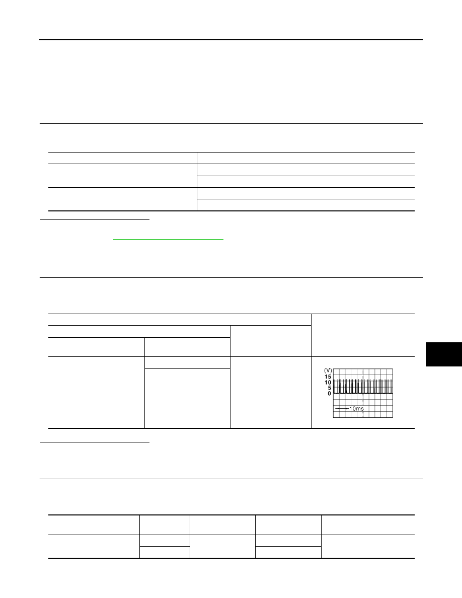
Terminal
Signal
(Reference value)
(+)
(–)
Door lock and unlock switch
connector
Terminal
M89
1
Ground
6
JPMIA0154GB
BCM connector
Terminal
Door lock and unlock
switch connector
Terminal
Continuity
M65
7
M89
6
Exists
9
1
DLK-74
< COMPONENT DIAGNOSIS >
[WITH I-KEY, WITHOUT SUPER LOCK]
DOOR LOCK AND UNLOCK SWITCH
Is the inspection result normal?
YES
>> GO TO 4.
NO
>> Repair or replace harness.
3.
CHECK DOOR LOCK AND UNLOCK SWITCH GROUND
Check continuity between door lock and unlock switch connector and ground.
Is the inspection result normal?
YES
>> GO TO 5.
NO
>> Repair or replace harness.
4.
CHECK BCM OUTPUT SIGNAL
1.
Connect BCM connector.
2.
Check voltage between BCM connector and ground.
Is the inspection result normal?
YES
>> Check intermittent incident. Refer to
GI-39, "Intermittent Incident"
.
NO
>> Replace BCM. Refer to
5.
CHECK DOOR LOCK AND UNLOCK SWITCH
Check door lock and unlock switch
Refer to
DLK-74, "Component Inspection"
Is the inspection result normal?
YES
>> Check intermittent incident. Refer to
GI-39, "Intermittent Incident"
.
NO
>> Replace door lock and unlock switch. Refer to
Component Inspection
INFOID:0000000001098047
1.
CHECK DOOR LOCK AND UNLOCK SWITCH
Check door lock and unlock switch.
Is the inspection result normal?
YES
>> Door lock and unlock switch is OK.
NO
>> Replace door lock and unlock switch. Refer to
BCM connector
Terminal
Ground
Continuity
M65
7
Does not exist
9
Door lock and unlock switch connector
Terminal
Ground
Continuity
M89
5
Exists
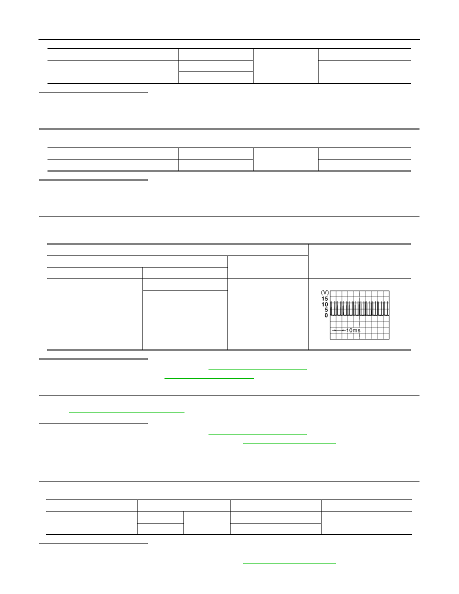
Terminal
Signal
(Reference value)
(+)
(–)
BCM connector
Terminal
M65
7
Ground
9
JPMIA0154GB
Door lock and unlock switch
Terminal
Condition
Continuity
M89
6
5
LOCK
Exists
1
UNLOCK
Нет комментариевНе стесняйтесь поделиться с нами вашим ценным мнением.
Текст