Nissan Qashqai (2007-2010). Manual — part 1425
PRECAUTIONS
INL-63
< PRECAUTION >
C
D
E
F
G
H
I
J
K
M
A
B
INL
N
O
P
PRECAUTION
PRECAUTIONS
Precaution for Supplemental Restraint System (SRS) "AIR BAG" and "SEAT BELT
PRE-TENSIONER"
INFOID:0000000001078350
The Supplemental Restraint System such as “AIR BAG” and “SEAT BELT PRE-TENSIONER”, used along
with a front seat belt, helps to reduce the risk or severity of injury to the driver and front passenger for certain
types of collision. This system includes seat belt switch inputs and dual stage front air bag modules. The SRS
system uses the seat belt switches to determine the front air bag deployment, and may only deploy one front
air bag, depending on the severity of a collision and whether the front occupants are belted or unbelted.
Information necessary to service the system safely is included in the SRC and SB section of this Service Man-
ual.
WARNING:
• To avoid rendering the SRS inoperative, which could increase the risk of personal injury or death in
the event of a collision which would result in air bag inflation, all maintenance must be performed by
an authorized NISSAN/INFINITI dealer.
• Improper maintenance, including incorrect removal and installation of the SRS, can lead to personal
injury caused by unintentional activation of the system. For removal of Spiral Cable and Air Bag
Module, see the SRC section.
• Do not use electrical test equipment on any circuit related to the SRS unless instructed to in this
Service Manual. SRS wiring harnesses can be identified by yellow and/or orange harnesses or har-
ness connectors.
INL-64
< ON-VEHICLE REPAIR >
MAP LAMP
ON-VEHICLE REPAIR
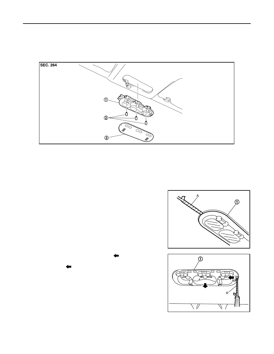
MAP LAMP
Exploded View
INFOID:0000000001033403
Removal and Installation
INFOID:0000000001080056
CAUTION:
Disconnect the battery negative terminal or the fuse.
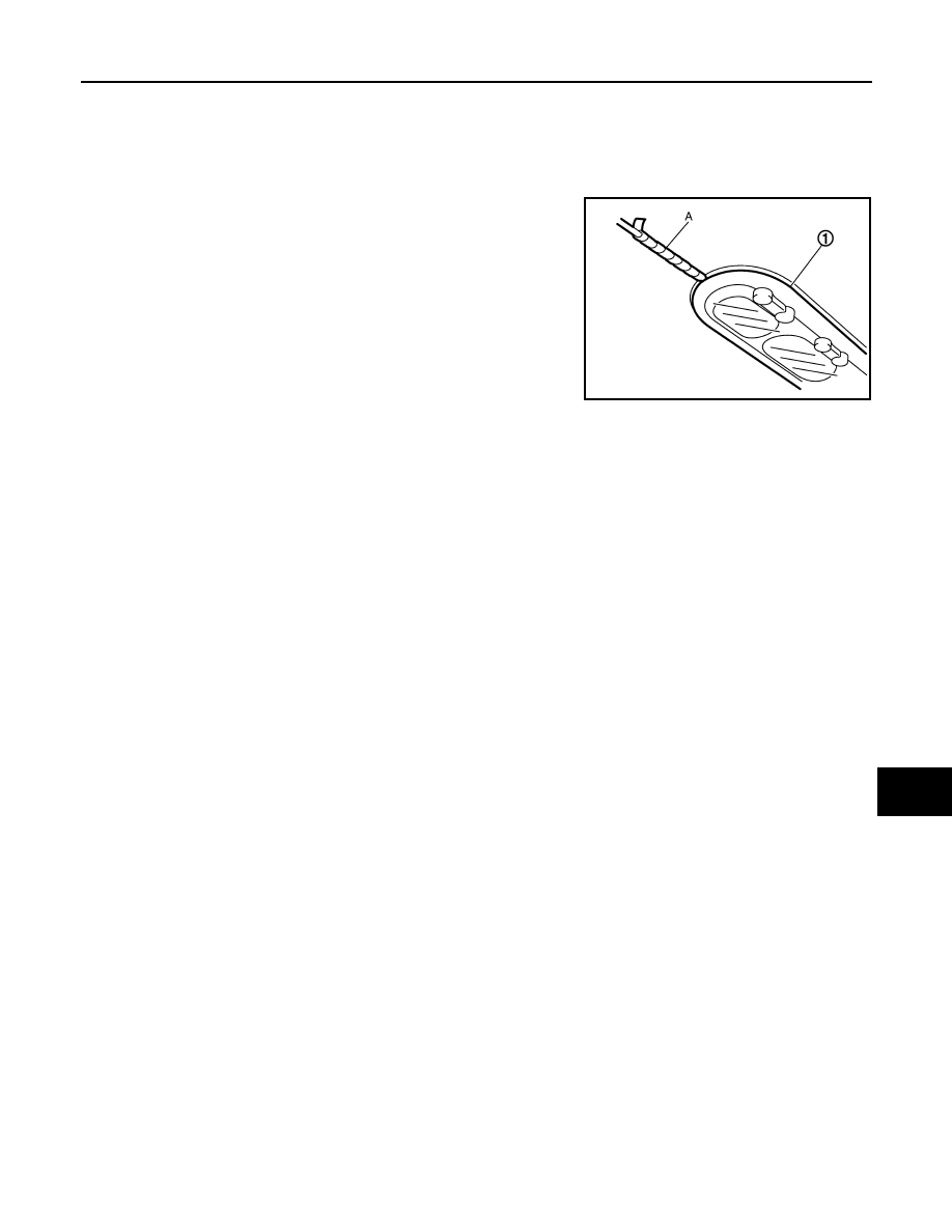
REMOVAL
1.
Insert any appropriate tool (A) into the gap between the lens (1)
and then remove the lens.
2.
Press the pawl to the arrow direction (
) with any appropriate
tool (A). And then pull the map lamp bulb housing (1) to the
arrow direction (
).
3.
Disconnect the connector, and remove the map lamp bulb hous-
ing.
INSTALLATION
Install in the reverse order of removal.
1.
Map lamp bulb housing
2.
Bulb
3.
Lens
JPLIA0264ZZ
MKIB2202E
MKIB2295E
MAP LAMP
INL-65
< ON-VEHICLE REPAIR >
C
D
E
F
G
H
I
J
K
M
A
B
INL
N
O
P
Replacement
INFOID:0000000001033405
CAUTION:
Disconnect the battery negative terminal or the fuse.
MAP LAMP BULB
1.
Insert any appropriate tool (A) into the gap between the lens (1)
and then remove the lens.
2.
Remove the bulb.
MKIB2202E
INL-66
< ON-VEHICLE REPAIR >
VANITY MIRROR LAMP
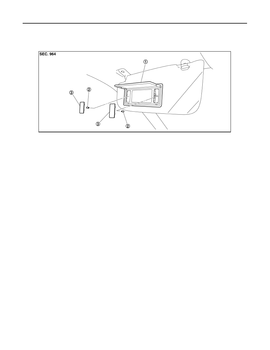
VANITY MIRROR LAMP
Exploded View
INFOID:0000000001033406
Replacement
INFOID:0000000001033407
CAUTION:
Disconnect the battery negative terminal or the fuse.
VANITY MIRROR LAMP BULB
1.
Insert any appropriate tool into the gap between the lens. Remove the lens.
2.
Remove the bulb.
1.
Vanity mirror assembly
2.
Bulb
3.
Lens
JPLIA0265ZZ
Нет комментариевНе стесняйтесь поделиться с нами вашим ценным мнением.
Текст