Nissan Qashqai (2007-2010). Manual — part 766
SBC-12
< COMPONENT DIAGNOSIS >
REAR SEAT BELT BUCKLE SWITCH
REAR SEAT BELT BUCKLE SWITCH
Description
INFOID:0000000001094017
• Detects if the seat belt is fastened or unfastened.
• Warning lamp turns OFF if the seat belt is fastened.
Component Function Check
INFOID:0000000001094018
1.
CHECK REAR SEAT BELT BUCKLE SWITCH FUNCTION
Check if the warning lamp turns OFF as soon as the seat belt is fastened.
Is the inspection results normal?
YES
>> Rear seat belt buckle switch is OK.
NO
>> Refer to
.
Diagnosis Procedure
INFOID:0000000001085566
1.
CHECK REAR SEAT BELT BUCKLE CIRCUIT
1.
Turn ignition switch ON.
2.
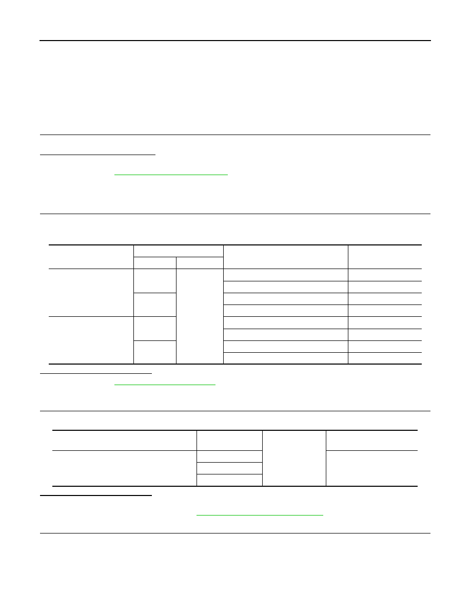
Check voltage between rear seat belt buckle switch and ground.
Is the inspection result normal?
YES
>> Refer to
GI-39, "Intermittent Incident"
.
NO
>> GO TO 2.
2.
CHECK INDICATOR UNIT OUTPUT SIGANL
Check voltage between indicator unit connector and ground.
Is the inspection result normal?
YES
>> GO TO 3.
NO
>> Replace indicator unit. Refer to
SBC-36, "Removal and Installation"
3.
CHECK REAR SEAT BELT BUCKLE SWITCH HARNESS
1.
Turn ignition switch OFF.
2.
Disconnect indictor unit and rear seat belt buckle switch connector.
3.
Check continuity between indictor unit and rear seat belt buckle switch harness connector.
Rear seat belt buckle
switch connector
Terminal
Condition
Voltage (V)
(Approx.)
(+)
(-)
B63 (LH and center)
1
Ground
Rear seat belt (LH) is fastened
Battery voltage
Rear seat belt (LH) is unfastened
0
3
Rear seat belt (center) is fastened
Battery voltage
Rear seat belt (center) is unfastened
0
B64 (RH and center)
1
Rear seat belt (RH) is fastened
Battery voltage
Rear seat belt (RH) is unfastened
0
3
Rear seat belt (center) is fastened
Battery voltage
Rear seat belt (center) is unfastened
0
Indicator unit connector
Terminal
Ground
Voltage (V)
(Approx.)
M91
3
Battery voltage
4
5
REAR SEAT BELT BUCKLE SWITCH
SBC-13
< COMPONENT DIAGNOSIS >
C
D
E
F
G
I
J
K
L
M
A
B
SBC
N
O
P
4.
Check continuity between indicator unit connector and ground.
Is the inspection result normal?
YES
>> GO TO 4.
NO
>> Repair or replace harness.
4.
CHECK GROUND CIRCUIT
Check continuity between rear sear belt buckle switch connector and ground.
Is the inspection result normal?
YES
>> GO TO 5.
NO
>> Repair or replace harness.
5.
CHECK REAR SEAT BELT BUKLE SWITCH
Check rear seat belt buckle switch.
Refer to
SBC-13, "Component Inspection"
.
Is the inspection result normal?
YES
>> Refer to
GI-39, "Intermittent Incident"
.
NO
>> Replace rear seat belt buckle switch. Refer to
SB-17, "SEAT BELT BUCKLE : Removal and Instal-
.
Component Inspection
INFOID:0000000001088995
1.
CHECK SEAT BELT BUCKLE SWITCH
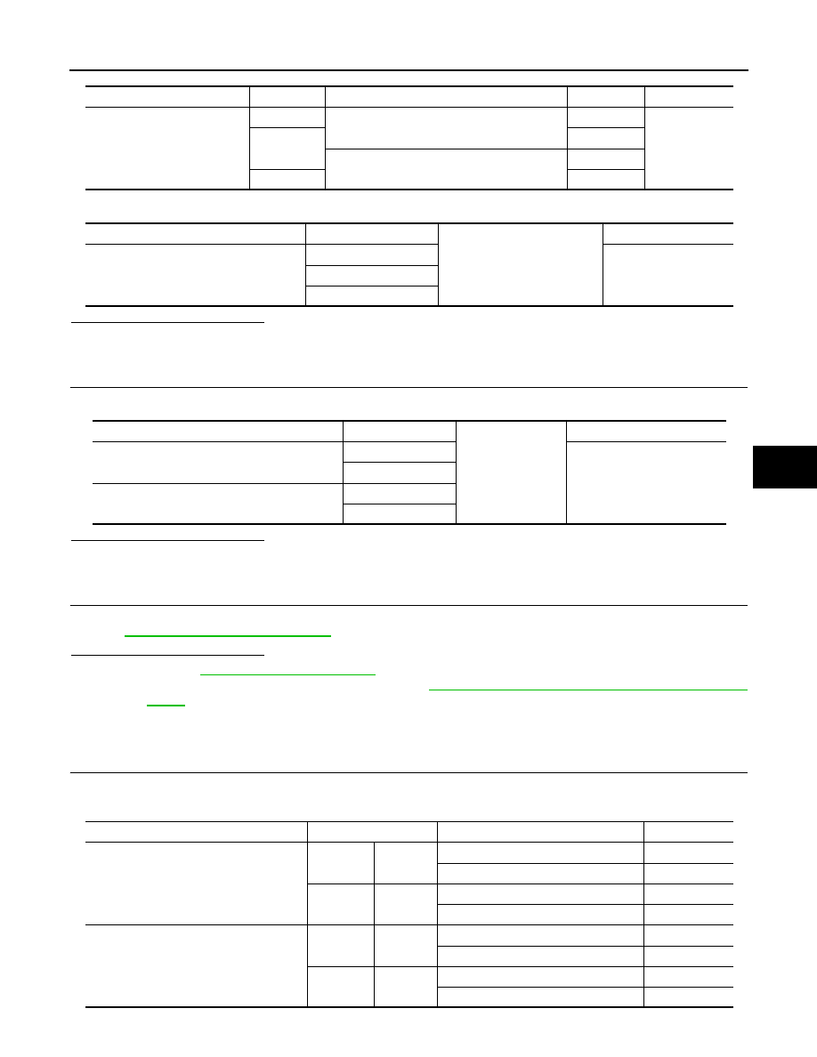
Check continuity between rear seat belt buckle switch while performing the insertion operation to the rear seat
belt buckle.
Indicator unit connector
Terminal
Rear seat belt buckle switch connector
terminal
Continuity
M91
3
B63 (LH and center)
1
Existed
4
3
B64 (RH and center)
3
5
1
Indicator unit connector
Terminal
Ground
Continuity
M91
3
Not existed
4
5
Rear seat belt buckle switch connector
Terminal
Ground
Continuity
B63 (LH and center)
2
Existed
4
B64 (RH and center)
2
4
Rear seat belt buckle switch connector
Terminal
Condition
Continuity
B63 (LH and center)
1
2
Rear seat belt (LH) is unfastened
Existed
Rear seat belt (LH) is fastened
Not existed
3
4
Rear seat belt (center) is unfastened
Existed
Rear seat belt (center) is fastened
Not existed
B64 (RH and center)
1
2
Rear seat belt (RH) is unfastened
Existed
Rear seat belt (RH) is fastened
Not existed
3
4
Rear seat belt (center) is unfastened
Existed
Rear seat belt (center) is fastened
Not existed
SBC-14
< COMPONENT DIAGNOSIS >
REAR SEAT BELT BUCKLE SWITCH
Is the inspection result normal?
YES
>> INSPECTION END.
NO
>> Replace seat belt buckle switch. Refer to
SB-17, "SEAT BELT BUCKLE : Removal and Installa-
.
ALTERNATOR SIGNAL CIRCUIT
SBC-15
< COMPONENT DIAGNOSIS >
C
D
E
F
G
I
J
K
L
M
A
B
SBC
N
O
P
ALTERNATOR SIGNAL CIRCUIT
Description
INFOID:0000000001080171
Transmits the “engine started” signal to indicator unit.
Component Function Check
INFOID:0000000001080172
1.
CHECK ALTERNATOR SIGNAL CIRCUIT
Check if the warning lamp turns OFF, approximately 35 seconds after the engine has started.
Is the inspection results normal?
YES
>> Alternator signal circuit is OK.
NO
>> Refer to
Diagnosis Procedure
INFOID:0000000001080173
1.
CHECK INDICATOR UNIT INPUT SIGNAL
1.
Turn ignition switch OFF.
2.
Disconnect indicator unit connector.
3.
Turn ignition switch ON.
4.
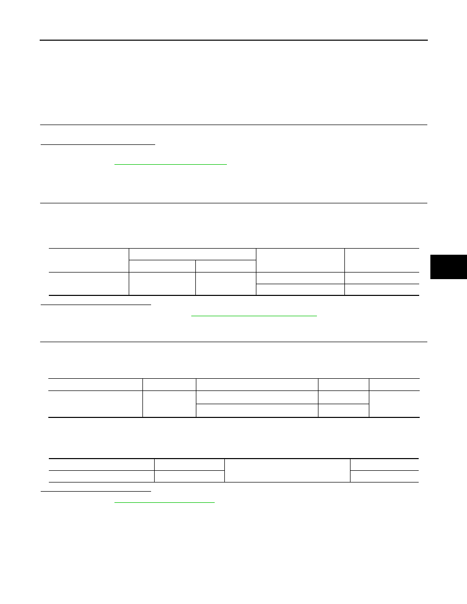
Check voltage between indicator unit harness connector and ground.
Is the inspection result normal?
YES
>> Replace indictor unit. Refer to
SBC-36, "Removal and Installation"
NO
>> GO TO 2.
2.
CHECK ALTERNATOR HARNESS
1.
Turn ignition switch OFF.
2.
Disconnect alternator connector.
3.
Check continuity between indictor unit and alternator harness connector.
*1
With gasoline engine
*2
With diesel engine
4.
Check continuity between indicator unit harness connector and ground.
Is the inspection result normal?
YES
>> Refer to
GI-39, "Intermittent Incident"
.
NO
>> Repair or replace harness.
Indictor unit connector
Terminal
Condition
Voltage (V)
(Approx.)
(+)
(-)
M91
6
Ground
Engine running
Battery voltage
Other than above
0
Indicator unit connector
Terminal
Alternator connector
terminal
Continuity
M91
6
R5
*1
3
*1
Existed
F60
*2
4
*2
Indicator unit connector
Terminal
Ground
Continuity
M91
6
Not existed
Нет комментариевНе стесняйтесь поделиться с нами вашим ценным мнением.
Текст