Nissan Qashqai (2007-2010). Manual — part 1946

AV-42
< BASIC INSPECTION >
[AUDIO WITH NAVIGATION]
DIAGNOSIS AND REPAIR WORKFLOW
Is any DTC No. displayed?
YES
>> GO TO 3.
NO
>> GO TO 4.
3.
CHECK SELF-DIAGNOSIS RESULTS (CONSULT-III)
1.
Check the DTC No. indicated in the self-diagnosis results.
2.
Perform the relevant diagnosis referring to the DTC Index. Refer to
NOTE:
Start with the diagnosis for the CAN communication system if “CAN COMM CIRCUIT [U1000] and CONTROL
UNIT CAN [U1010]” is displayed.
>> GO TO 5.
4.
PERFORM DIAGNOSIS BY SYMPTOM
Perform the relevant diagnosis referring to the diagnosis chart by symptom. Refer to
.
>> GO TO 5.
5.
REPAIR OR REPLACE MALFUNCTIONING PARTS
Repair or replace the identified malfunctioning parts.
NOTE:
Erase the stored self-diagnosis results after repairing or replacing the relevant components if any DTC No. has
been indicated in the self-diagnosis results.
>> GO TO 6.
6.
CHECK AFTER REPAIR
1.
Perform a self-diagnosis for “MULTI AV” with CONSULT-III after repairing or replacing the malfunctioning
parts.
2.
Check that any DTC No. is displayed in the self-diagnosis results.
Is any DTC No. displayed?
YES
>> GO TO 3.
NO
>> GO TO 7.
7.
FINAL CHECK
Perform the operation to check that the malfunction symptom is solved or any other symptoms are present.
Is there any symptom?
YES
>> GO TO 4.
NO
>> INSPECTION END

AV
MULTI AV SYSTEM
AV-43
< FUNCTION DIAGNOSIS >
[AUDIO WITH NAVIGATION]
C
D
E
F
G
H
I
J
K
L
M
B
A
O
P
FUNCTION DIAGNOSIS
MULTI AV SYSTEM
System Diagram
INFOID:0000000000947003
System Description
INFOID:0000000000947004
Multi AV system means that the following systems are integrated.
• Two AV communication lines (H, L) connect between units that configure MULTI AV system. NAVI control
unit controls by sending/receiving data one by one with each unit (slave unit) that configures them com-
pletely as a master unit.
• Two AV communication lines (H, L) adopt a twisted pair line that is resistant to noise.
• NAVI control unit is connected by CAN communication, and it receives data signal from ECM, combination
meter. It computes and displays fuel economy information value with the obtained information. Sending/
receiving of data signal is performed by BCM. Also, it sends the required signal of vehicle setting and
receives the response signal.
JPNIA0153GB
System name
System explanation
NAVIGATION SYSTEM
AUDIO SYSTEM
REAR VIEW MONITOR SYSTEM
VEHICLE INFORMATION SYSTEM
• Status of audio, fuel economy, maintenance and navigation is
displayed.
• NAVI control unit displays the fuel consumption status and trip
computer status while receiving data signal through CAN com-
munication from ECM, combination meter and BCM.
HANDS-FREE PHONE SYSTEM
Refer to the following “HANDS-FREE PHONE SYSTEM”.

AV-44
< FUNCTION DIAGNOSIS >
[AUDIO WITH NAVIGATION]
MULTI AV SYSTEM
• NAVI control unit is connected with display and serial communication, and it sends the required signal of dis-
play and display control and receives the response signal from front display. Also, it is connected with satel-
lite radio by serial communication, and it sends the operating signal and receives the display signal.
NOTE:
NAVI control unit can perform CONSULT-III self-operating function and on board self-diagnosis.
• CONSULT-III self diagnosis: Refer to
AV-65, "CONSULT - III Function (MULTI AV)"
• On board self diagnosis: Refer to
AV-55, "Diagnosis Description"
.
HANDS-FREE PHONE SYSTEM
• Hands-free communication can be operated by connecting using Bluetooth
®
with cellular phone.
• Operation is performed by steering switch, and operating condition is indicated on display.
• Guide sound that is heard during operation is input from NAVI control unit to audio unit and is output from
front speaker.
When a call is originated
Spoken voice sound output from the microphone (Mic. Signal) is input to NAVI control unit. NAVI control unit
outputs to cellular phone with Bluetooth
®
communication as a TEL voice signal. Voice sound is then heard at
the other party.
When receiving a call
Voice sound is input to own cellular phone from the other party. TEL voice signal is output to front speaker, and
the signal is input to audio unit via NAVI control unit by establishing Bluetooth
®
communication from cellular
phone.
Component Parts Location
INFOID:0000000000947005
NOTE:
As for right-hand drive vehicles, install GPS antenna feeder between the center console and the instrument
panel in the reverse of left-handle drive vehicles.
JPNIA0155GB
AV
MULTI AV SYSTEM
AV-45
< FUNCTION DIAGNOSIS >
[AUDIO WITH NAVIGATION]
C
D
E
F
G
H
I
J
K
L
M
B
A
O
P
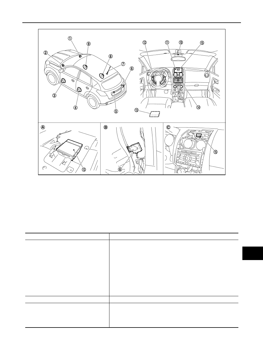
Component Description
INFOID:0000000000947006
1.
Tweeter RH
2.
Tweeter LH
3.
Front door speaker LH
4.
Rear door speaker LH
5.
Rear view camera
6.
Camera control unit
7.
Radio antenna
8.
Rear door speaker RH
9.
Front door speaker RH
10. Microphone
11. Display unit
12. Steering switch
13. NAVI control unit
14. Audio unit
15. GPS antenna
A.
A bottom of a front seat LH
B.
Luggage side RH
C.
Back of a display unit
JSNIA0349ZZ
Part name
Description
NAVI CONTORL UNIT
• Map data can be read from the Map DVD-ROM by installing Map DVD-ROM.
• It is the master unit of the MULTI AV system, and it is connected to each con-
trol unit by means of communication. It operates each system according to
communication signals from the NAVI control unit.
• The NAVI control unit includes the audio, hands-free phone, navigation, and
vehicle information functions.
• It is connected to ECM and combination meter via CAN communication to ob-
tain necessary information for the vehicle information function.
• It inputs the illumination signals that are required for the display dimming con-
trol.
• It inputs the signals for driving status recognition (vehicle speed, reverse and
parking brake).
MAP DVD-ROM
A collection of Map data.
DISPLAY UNIT
• Display image is controlled by the serial communication from NAVI control
unit.
• RGB image signal is input from NAVI control unit (RGB, RGB area and RGB
synchronizing). Camera image signal is input from camera control unit.
• Synchronize signal (HP, VP) is output to NAVI control unit.
Нет комментариевНе стесняйтесь поделиться с нами вашим ценным мнением.
Текст