Nissan Qashqai (2007-2010). Manual — part 933
HAC-92
< ECU DIAGNOSIS >
[AUTOMATIC AIR CONDITIONER]
ECM
MR20DE : Reference Value
INFOID:0000000001116979
VALUES ON THE DIAGNOSIS TOOL
Remarks:
l
Specification data are reference values.
l
Specification data are output/input values which are detected or supplied by the ECM at the connector.
* Specification data may not be directly related to their components signals/values/operations.
I.e. Adjust ignition timing with a timing light before monitoring IGN TIMING, because the monitor may show the specification data in spite of the
ignition timing not being adjusted to the specification data. this IGN TIMING monitors the data calculated by the ECM according to the signals
input from the camshaft position sensor and other ignition timing related sensors.
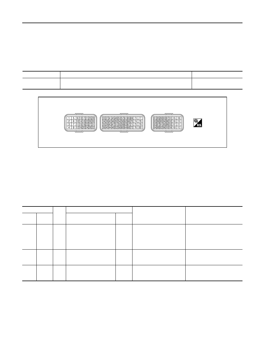
TERMINAL LAYOUT
PHYSICAL VALUES
NOTE:
• ECM is located behind the passenger side instrument lower panel. For this inspection, remove passenger
side instrument lower panel.
• Specification data are reference values and are measured between each terminal and ground.
• Pulse signal is measured by CONSULT-III.
CAUTION:
Do not use ECM ground terminals when measuring input/output voltage. Doing so may result in dam-
age to the ECMs transistor. Use a ground other than ECM terminals, such as the ground.
K9K
K9K : Reference Value
INFOID:0000000001116980
VALUE ON THE DIAGNOSIS TOOL
Remarks:
l
Specification data are reference values.
l
Specification data are output/input values which are detected or supplied by the ECM at the connector.
Monitor Item
Condition
Values/Status
AC PRESS SEN
• Engine: Idle
• Both A/C switch and blower fan switch: ON (Compressor operates)
1.0 - 4.0 V
PBIA9221J
Terminal No.
Wire
color
Description
Condition
Value
(Approx.)
+
-–
Signal name
Input/
Output
41
Ground
G
Refrigerant pressure sensor
Input
[Engine is running]
• Warm-up condition
• Both A/C switch and blower
fan motor switch: ON (Com-
pressor operates)
1.0 - 4.0 V
48
Ground
R/B
Sensor ground
(Refrigerant pressure sen-
sor)
—
[Engine is running]
• Warm-up condition
• Idle speed
0 V
74
Ground
L
Sensor power supply
(Refrigerant pressure sen-
sor)
Input
[Ignition switch: ON]
5 V
ECM
HAC-93
< ECU DIAGNOSIS >
[AUTOMATIC AIR CONDITIONER]
C
D
E
F
G
H
J
K
L
M
A
B
HAC
N
O
P
* Specification data may not be directly related to their components signals/values/operations.
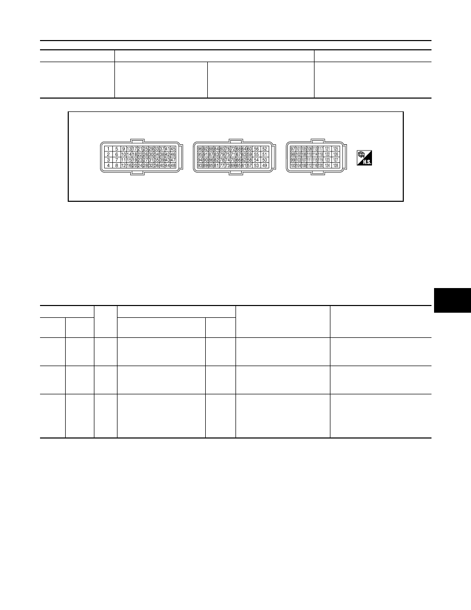
TERMINAL LAYOUT
PHYSICAL VALUES
NOTE:
• ECM is located behind the passenger side instrument lower panel. For this inspection, remove passenger
side instrument lower panel.
• Specification data are reference values and are measured between each terminal and ground.
• Pulse signal is measured by CONSULT-III.
CAUTION:
Do not use ECM ground terminals when measuring input/output voltage. Doing so may result in dam-
age to the ECMs transistor. Use a ground other than ECM terminals, such as the ground.
MONITOR ITEM
CONDITION
SPECIFICATION
RFRGERNT PRSS
• Engine: After warming up
• Air conditioner switch: OFF
• Shift lever: Neutral position
• No load
Idle
Approximately 5.7 bar
JMBIA0417ZZ
Terminal No.
Wire
color
Description
Condition
Value
(Approx.)
+
-–
Signal name
Input/
Output
74
Ground
R/L
Sensor power supply
(Refrigerant pressure sen-
sor)
—
[Ignition switch: ON]
Approximately 5.0 V
78
Ground
R/B
Sensor ground
(Refrigerant pressure sen-
sor)
G/P
[Engine is running]
• Warm-up condition
• Idle speed
Approximately 0.3 V
89
Ground
Y/W
Refrigerant pressure sensor
Input
[Engine is running]
• Warm-up condition
• Both A/C switch and blower
fan switch: ON (Compressor
operates)
Approximately2.3 V
HAC-94
< ECU DIAGNOSIS >
[AUTOMATIC AIR CONDITIONER]
BCM (BODY CONTROL MODULE)
BCM (BODY CONTROL MODULE)
Reference Value
INFOID:0000000001116981
VALUES ON THE DIAGNOSIS TOOL
Monitor Item
Condition
Value/Status
AIR COND SW
A/C switch OFF
Off
A/C switch ON
On
FAN ON SIG
Fan switch OFF
Off
Fan switch ON
On
IGN ON SW
Ignition switch OFF or ACC
Off
Ignition switch ON
On
BCM (BODY CONTROL MODULE)
HAC-95
< ECU DIAGNOSIS >
[AUTOMATIC AIR CONDITIONER]
C
D
E
F
G
H
J
K
L
M
A
B
HAC
N
O
P
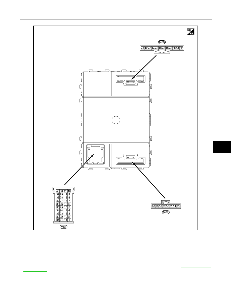
TERMINAL LAYOUT
PHYSICAL VALUES
CAUTION:
• Check combination switch system terminal waveform under the loaded condition with lighting
switch, turn signal switch and wiper switch OFF is not to be fluctuated by being overloaded.
• Turn wiper intermittent dial position to 4 except when checking waveform or voltage of wiper inter-
mittent dial position. Wiper intermittent dial position can be confirmed on CONSULT -III. Refer to
BCS-26, "COMB SW : CONSULT-III Function (BCM - COMB SW)"
• BCM reads the status of the combination switch at 10ms internal normally. Refer to
JPMIA0145GB
Нет комментариевНе стесняйтесь поделиться с нами вашим ценным мнением.
Текст