Nissan Qashqai (2007-2010). Manual — part 854
INTAKE DOOR MOTOR
VTL-81
< ON-VEHICLE REPAIR >
[MANUAL AIR CONDITIONER]
C
D
E
F
G
H
J
K
L
M
A
B
VTL
N
O
P
INTAKE DOOR MOTOR
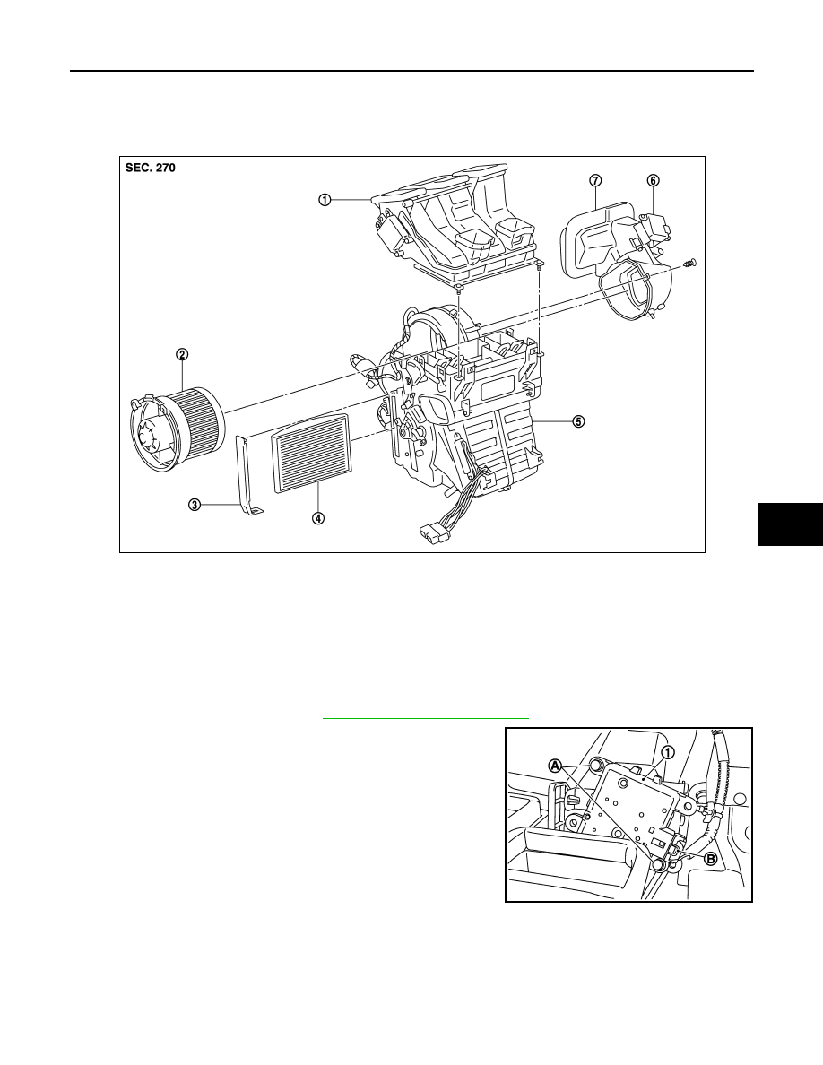
Exploded View
INFOID:0000000001093846
Removal and Installation
INFOID:0000000001093847
REMOVAL
1.
Remove Instrument Panel. Refer to
IP-12, "Removal and Installation"
2.
Disconnect intake door motor connector (B).
3.
Remove harness connector fixing clip.
4.
Remove intake door motor fixing screws (A).
5.
Remove intake door motor (1).
INSTALLATION
Installation is basically the reverse order of removal.
1.
Hi-Level ventilation door unit assem-
bly
2.
Blower motor assembly
3.
Filter cover
4.
In-cabin microfilter
5.
Blower unit
6.
Intake door motor
7.
Intake door unit assembly
E1IIA0002GB
E1IIA0017ZZ
VTL-82
< ON-VEHICLE REPAIR >
[MANUAL AIR CONDITIONER]
HEATER & COOLING UNIT ASSEMBLY
HEATER & COOLING UNIT ASSEMBLY
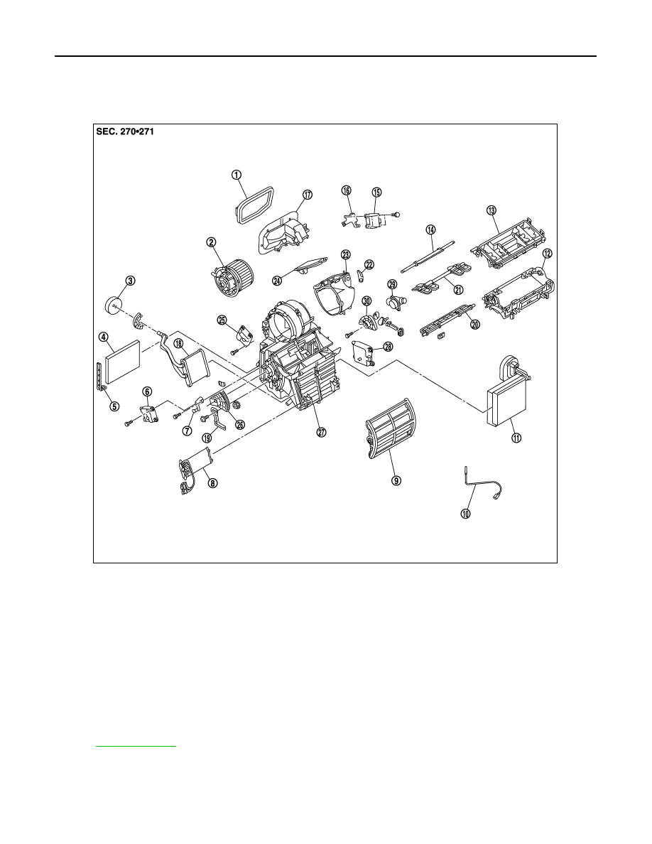
Exploded View
INFOID:0000000001093848
Removal and Installation
INFOID:0000000001093849
REMOVAL
1.
Intake connector seal
2.
Blower motor assembly
3.
Heater pipe seal
4.
Air conditioner filter
5.
Air conditioner filter cover
6.
Air mix door motor (left)
7.
Air mix door lever
8.
Electrical heater
9.
Air mix door (slide door)
10. Intake sensor
11.
Evaporator and expansion valve unit
12.
Center case (lower)
13. Center case (upper)
14.
Defroster door
15.
Intake door motor
16. Intake motor bracket
17.
Intake connector
18.
Heater core
19. Air mix door link bracket
20.
Front ventilator door
21.
Side ventilator door
22. Intake door lever
23.
Intake door box
24.
Intake door
25. Mode door motor
26.
Air mix door link (left)
27.
Heater and cooling unit case
28. Air mix door motor (right)
29.
Aspirator
30.
Air mix door link (right)
*
With left and right ventilation temperature separately system.
for symbols in the figure.
E1IIA0008GB
HEATER & COOLING UNIT ASSEMBLY
VTL-83
< ON-VEHICLE REPAIR >
[MANUAL AIR CONDITIONER]
C
D
E
F
G
H
J
K
L
M
A
B
VTL
N
O
P
1.
Use a refrigerant collecting equipment (for HFC-134a) to discharge the refrigerant.
2.
Drain engine coolant from cooling system. Refer to
(K9K).
3.
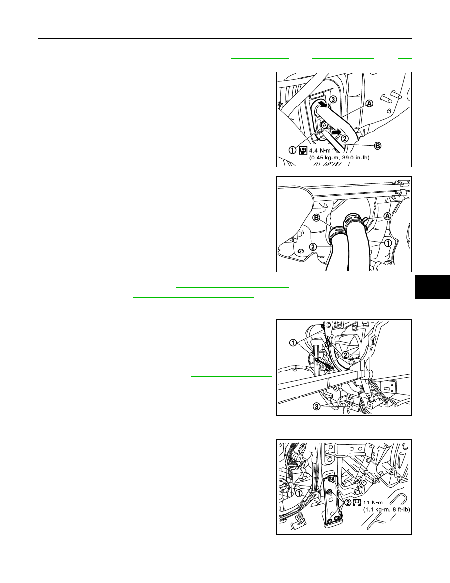
Remove pipe bracket fixing bolt (1), then, disconnect high-pres-
sure pipe 1 (B) and low-pressure pipe 2 (A) from expansion
valve.
CAUTION:
Cap or wrap the joint of high-pressure pipe 1 and low-pres-
sure pipe 2 with suitable material such as vinyl tape to
avoid the entry of air.
4.
Remove clamp (A), then disconnect heater hoses (1), and then
remove clamp (B), to remove heater hose (2).
5.
Remove Instrument Panel. Refer to
IP-12, "Removal and Installation"
6.
Remove BCM.Refer to
BCS-64, "Removal and Installation"
• Remove fixing screws.
• Remove harness connectors.
7.
Disconnect heater connectors (3), then remove heater connec-
tor and bracket.
8.
Disconnect blower motor connector.
9.
Remove heater control cables from heater and cooling unit (1).
10. Remove foot duct, RH.
11. Remove power steering C/U. Refer to
.
12. Disconnect intake door motor connector and blower motor con-
nector.
13. Remove center air duct.
14. Remove blower intake motor connector and remove harness fix-
ing clip.
15. Remove instrument stay (1).
16. Remove fixing nuts (2).
17. Remove heater draining hose.
E1IIA0011GB
E1IIA0012ZZ
E1IIA0020ZZ
E1IIA0013GB
V
T
L
- 8
4
< ON-VEHICLE REPAIR >
[MANUAL AIR CONDITIONER]
HEATER & COOLING UNIT ASSEMBLY
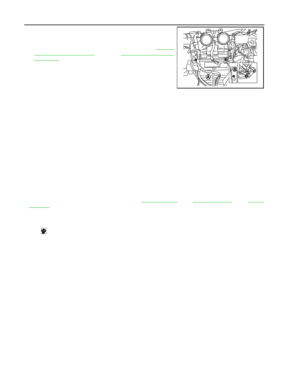
18. Remove heater and cooling assembly lower fixing bolts (B), RH
side.
19. Remove heater and cooling assembly upper fixing bolts (A).
20. Remove high and low pressure pipes. Refer to
(K9K).
21. Remove clips of main harness from steering member.
22. Remove steering member mounting bolts.
• Disconnect harness fixing clips from steering member
NOTE:
Two workers are necessary to remove this part.
23. Remove heater and cooling unit assembly.
INSTALLATION
Installation is basically the reverse order of removal.
CAUTION:
• Replace O-rings of low-pressure pipe 1, 2 and high-pressure pipe 1, 2 with new ones, and then apply
compressor oil to it when installing it.
• Female-side piping connection is thin and easy to deform. Slowly insert the male-side piping
straight in axial direction.
• Insert piping securely until a clicks is heard.
• After piping connection is completed, pull male-side piping by hand to make sure that connection
does not come loose.
• When recharging refrigerant, check for leaks.
NOTE:
• When filling radiator with engine coolant. Refer to
• Recharge the refrigerant.
E1IIA0015ZZ
Heater & cooling unit (1) assembly mounting bolt (A)
: 6.9 N·m (0.7 kg·m, 61 in-lb)
Нет комментариевНе стесняйтесь поделиться с нами вашим ценным мнением.
Текст