Nissan Qashqai (2007-2010). Manual — part 171
P0420 THREE WAY CATALYST FUNCTION
EC-203
< COMPONENT DIAGNOSIS >
[HR16DE (WITH EURO-OBD)]
C
D
E
F
G
H
I
J
K
L
M
A
EC
N
P
O
Is the inspection result normal?
YES
>> INSPECTION END
NO
>> If the ratio is greater than above (0.75), it means three way catalyst does not operate properly. Go
to
.
Diagnosis Procedure
INFOID:0000000001056308
1.
CHECK EXHAUST SYSTEM
Visually check exhaust tubes and muffler for dent.
Is the inspection result normal?
YES
>> GO TO 2.
NO
>> Repair or replace.
2.
CHECK EXHAUST GAS LEAK
1.
Start engine and run it at idle.
2.
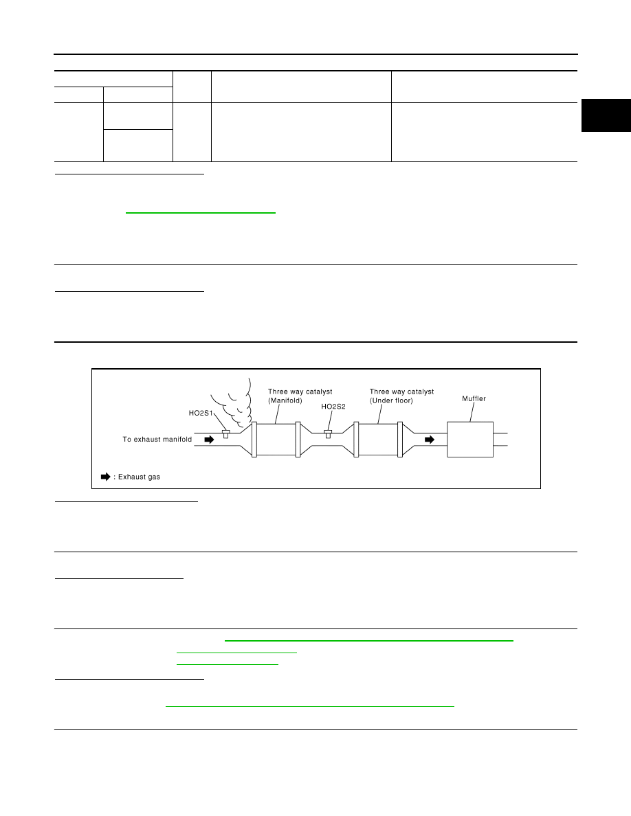
Listen for an exhaust gas leak before the three way catalyst (manifold).
Is exhaust gas leak detected?
YES
>> Repair or replace.
NO
>> GO TO 3.
3.
CHECK INTAKE AIR LEAK
Listen for an intake air leak after the mass air flow sensor.
Is intake air leak detected?
YES
>> Repair or replace.
NO
>> GO TO 4.
4.
CHECK IGNITION TIMING AND IDLE SPEED
Check the following items. Refer to
EC-26, "BASIC INSPECTION : Special Repair Requirement"
.
Is the inspection result normal?
YES
>> GO TO 5.
NO
>> Follow the
EC-26, "BASIC INSPECTION : Special Repair Requirement"
.
5.
CHECK FUEL INJECTOR
1.
Stop engine and then turn ignition switch ON.
2.
Check the voltage between ECM harness connector and ground.
ECM
Ground
Condition
Specification
Connector
Terminal
F8
49
(HO2S1 signal)
Ground
Keeping engine speed at 2,000 rpm constant
under no load
Switching freqency ratio ( A/B) : Less than 0.75
A : Heated oxygen sensor 2 voltage switching
frequency
B : Heated oxygen sensor 1 voltage switching
frequency
50
(HO2S2 signal)
SEC502D
EC-204
< COMPONENT DIAGNOSIS >
[HR16DE (WITH EURO-OBD)]
P0420 THREE WAY CATALYST FUNCTION
Is the inspection result normal?
YES
>> GO TO 6.
NO
>> Perform
.
6.
CHECK FUNCTION OF IGNITION COIL-I
CAUTION:
Do the following procedure in the place where ventilation is good without the combustible.
1.
Turn ignition switch OFF.
2.
Remove fuel pump fuse in IPDM E/R to release fuel pressure.
NOTE:
Do not use CONSULT-III to release fuel pressure, or fuel pressure applies again during the following pro-
cedure.
3.
Start engine.
4.
After engine stalls, crank it two or three times to release all fuel pressure.
5.
Turn ignition switch OFF.
6.
Remove all ignition coil harness connectors to avoid the electrical discharge from the ignition coils.
7.
Remove ignition coil and spark plug of the cylinder to be checked.
8.
Crank engine for 5 seconds or more to remove combustion gas in the cylinder.
9.
Connect spark plug and harness connector to ignition coil.
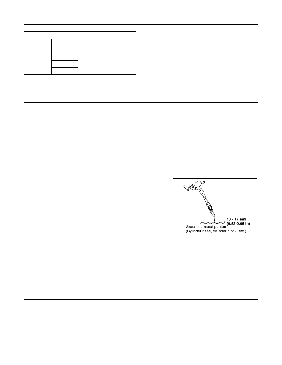
10. Fix ignition coil using a rope etc. with gap of 13 - 17 mm (0.52 -
0.66 in) between the edge of the spark plug and grounded metal
portion as shown in the figure.
11. Crank engine for about 3 seconds, and check whether spark is
generated between the spark plug and the grounded metal por-
tion.
CAUTION:
• Do not approach to the spark plug and the ignition coil
within 50 cm (19.7 in). Be careful not to get an electrical
shock while checking, because the electrical discharge
voltage becomes 20kV or more.
• It might cause to damage the ignition coil if the gap of more than 17 mm (0.66 in) is taken.
NOTE:
When the gap is less than 13 mm (0.52 in), the spark might be generated even if the coil is mal-
functioning.
Is the inspection result normal?
YES
>> GO TO 10.
NO
>> GO TO 7.
7.
CHECK FUNCTION OF IGNITION COIL-II
1.
Turn ignition switch OFF.
2.
Disconnect spark plug and connect a known-good spark plug.
3.
Crank engine for about 3 seconds, and recheck whether spark is generated between the spark plug and
the grounded metal portion.
Is the inspection result normal?
YES
>> GO TO 8.
ECM
Ground
Voltage
Connector
Terminal
F7
31
Ground
Battery voltage
30
29
25
Spark should be generated.
JMBIA0066GB
Spark should be generated.
P0420 THREE WAY CATALYST FUNCTION
EC-205
< COMPONENT DIAGNOSIS >
[HR16DE (WITH EURO-OBD)]
C
D
E
F
G
H
I
J
K
L
M
A
EC
N
P
O
NO
>> Check ignition coil, power transistor and their circuits. Refer to
.
8.
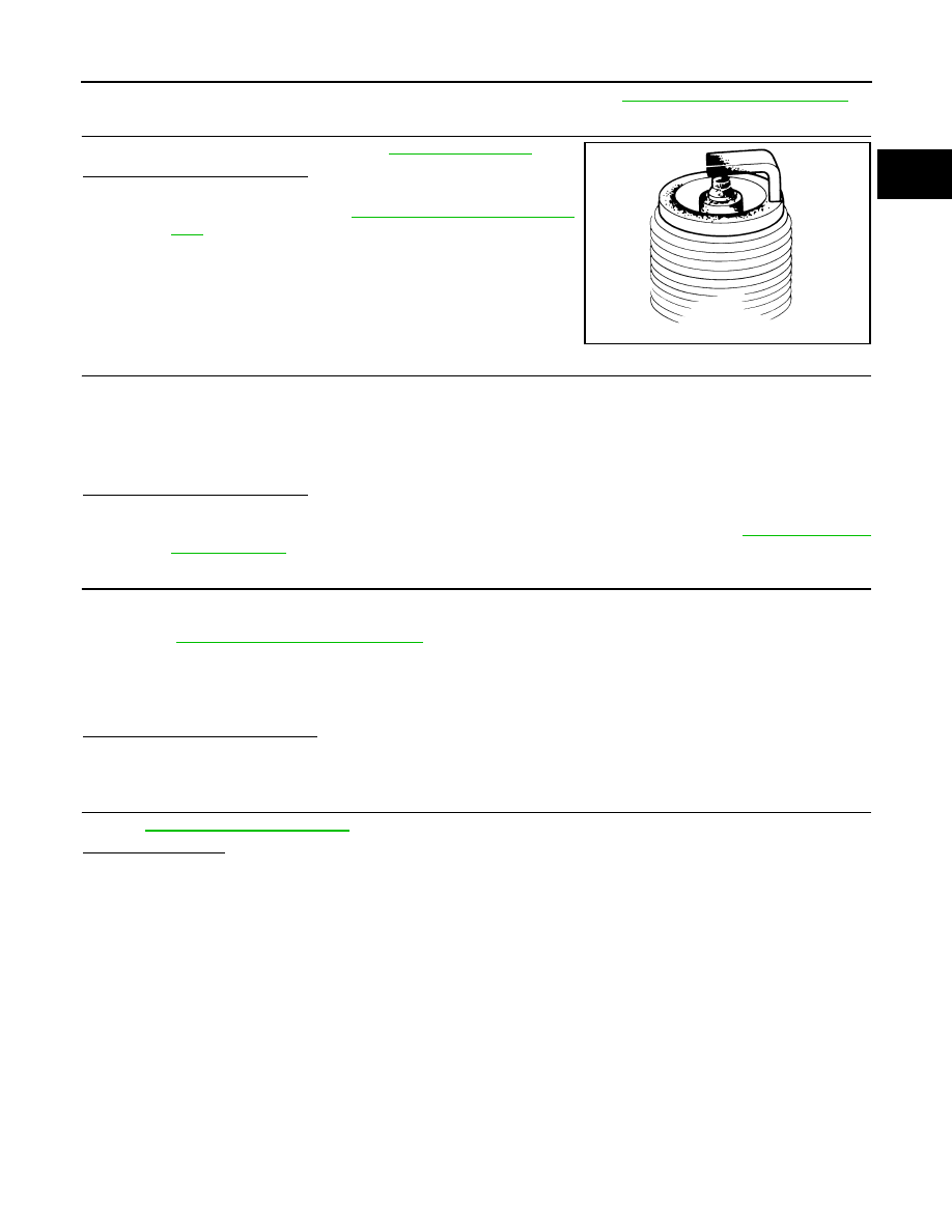
CHECK SPARK PLUG
Check the initial spark plug for fouling, etc.
Is the inspection result normal?
YES
>> Replace spark plug(s) with standard type one(s). For
.
NO
>> Repair or clean spark plug. Then GO TO 9
9.
CHECK FUNCTION OF IGNITION COIL-III
1.
Reconnect the initial spark plugs.
2.
Crank engine for about three seconds, and recheck whether spark is generated between the spark plug
and the grounded portion.
Is the inspection result normal?
YES
>> INSPECTION END
NO
>> Replace spark plug(s) with standard type one(s). For spark plug type, refer to
.
10.
CHECK FUEL INJECTOR
1.
Turn ignition switch OFF.
2.
Remove fuel injector assembly.
Refer to
EM-35, "Removal and Installation"
Keep fuel hose and all fuel injectors connected to fuel tube.
3.
Disconnect all ignition coil harness connectors.
4.
Reconnect all fuel injector harness connectors disconnected.
5.
Turn ignition switch ON.
Does fuel drip from fuel injector?
YES
>> GO TO 11.
NO
>> Replace the fuel injector(s) from which fuel is dripping.
11.
CHECK INTERMITTENT INCIDENT
GI-39, "Intermittent Incident"
.
Is the trouble fixed?
YES
>> INSPECTION END
NO
>> Replace three way catalyst assembly.
SEF156I
Spark should be generated.
EC-206
< COMPONENT DIAGNOSIS >
[HR16DE (WITH EURO-OBD)]
P0444 EVAP CANISTER PURGE VOLUME CONTROL SOLENOID VALVE
P0444 EVAP CANISTER PURGE VOLUME CONTROL SOLENOID VALVE
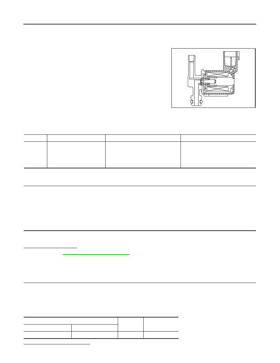
Description
INFOID:0000000001056319
The EVAP canister purge volume control solenoid valve uses a ON/
OFF duty to control the flow rate of fuel vapor from the EVAP canis-
ter. The EVAP canister purge volume control solenoid valve is
moved by ON/OFF pulses from the ECM. The longer the ON pulse,
the greater the amount of fuel vapor that will flow through the valve.
DTC Logic
INFOID:0000000001056320
DTC DETECTION LOGIC
DTC CONFIRMATION PROCEDURE
1.
CONDITIONING
If DTC Confirmation Procedure has been previously conducted, always turn ignition switch OFF and wait at
least 10 seconds before conducting the next test.
TESTING CONDITION:
Before performing the following procedure, confirm battery voltage is more than 11V at idle.
>> GO TO 2.
2.
PERFORM DTC CONFIRMATION PROCEDURE
1.
Start engine and let it idle for at least 13 seconds.
2.
Check 1st trip DTC.
Is 1st trip DTC detected?
YES
>> Go to
NO
>> INSPECTION END
Diagnosis Procedure
INFOID:0000000001056321
1.
CHECK EVAP CANISTER PURGE VOLUME CONTROL SOLENOID VALVE POWER SUPPLY CIRCUIT
1.
Turn ignition switch OFF.
2.
Disconnect EVAP canister purge volume control solenoid valve harness connector.
3.
Turn ignition switch ON.
4.
Check the voltage between EVAP canister purge volume control solenoid valve harness connector and
ground.
Is the inspection result normal?
PBIA9215J
DTC No.
Trouble diagnosis name
DTC detecting condition
Possible cause
P0444
EVAP canister purge volume
control solenoid valve circuit
open
An excessively low voltage signal is sent
to ECM through the valve
• Harness or connectors
(The solenoid valve circuit is open or
shorted.)
• EVAP canister purge volume control so-
lenoid valve
EVAP canister purge volume control solenoid valve
Ground
Voltage
Connector
Terminal
F32
1
Ground
Battery voltage
Нет комментариевНе стесняйтесь поделиться с нами вашим ценным мнением.
Текст