Nissan Qashqai (2007-2010). Manual — part 679
FRONT DISC BRAKE
BR-15
< ON-VEHICLE MAINTENANCE >
[LHD]
C
D
E
G
H
I
J
K
L
M
A
B
BR
N
O
P
FRONT DISC BRAKE
BRAKE PAD
BRAKE PAD : Exploded View
INFOID:0000000000925781
BR-37, "BRAKE CALIPER ASSEMBLY : Exploded View"
.
BRAKE PAD : Inspection
INFOID:0000000000925782
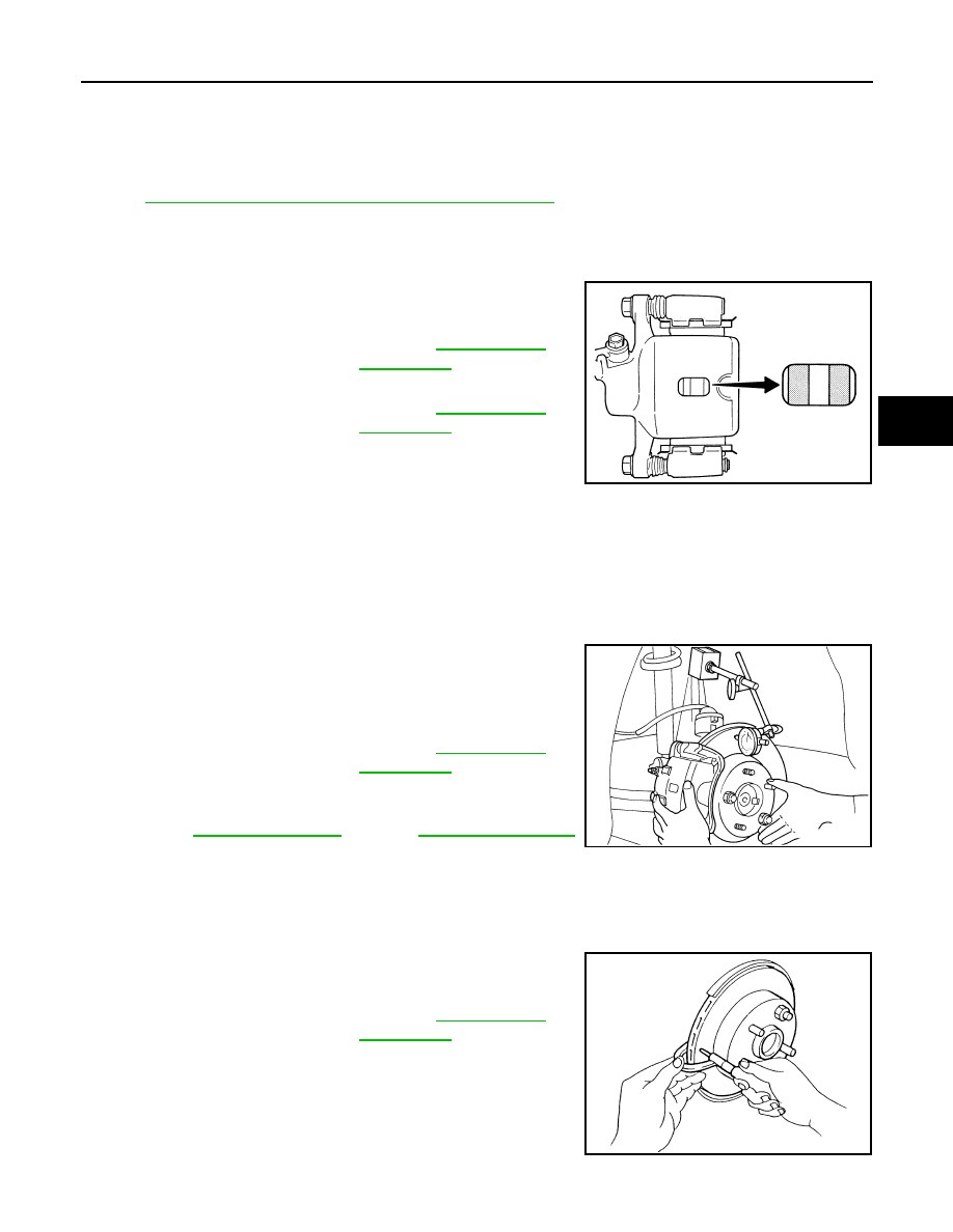
PAD WEAR
Check pad thickness from an inspection hole on cylinder body.
Check using a scale if necessary.
DISC ROTOR
DISC ROTOR : Inspection
INFOID:0000000000925783
APPEARANCE
Check surface of disc rotor for uneven wear, cracks, and serious damage. Replace if there are.
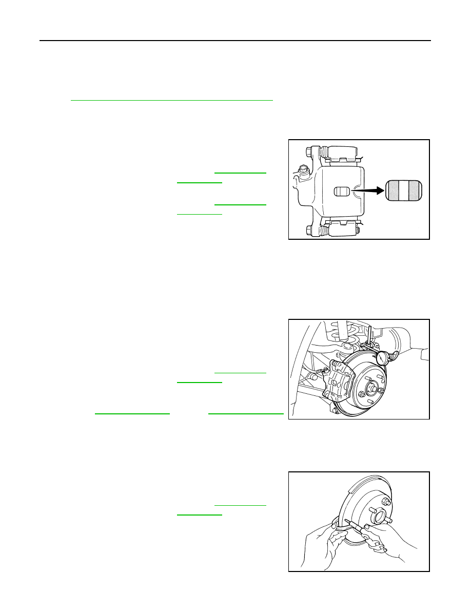
RUNOUT
1.
Fix the disc rotor to the wheel hub and bearing assembly with
wheel nuts (2 points at least).
2.
Inspect the runout with a dial gauge. [Measured at 10 mm (0.39
in) inside the disc edge.]
NOTE:
Check the wheel bearing axial end play before the inspection.
Refer to
(4WD).
3.
Find the installation position with a minimum runout by shifting the disc rotor-to-wheel hub and bearing
assembly installation position by one hole at a time if the runout exceeds the limit value.
4.
Replace or lathe the disc rotor if the runout exceeds the limit even after the above operation.
THICKNESS
Check the thickness of the disc rotor using a micrometer. Replace
the disc rotor if the thickness is below the wear limit.
Standard thickness
: Refer to
.
Wear limit thickness
: Refer to
.
BRA0010D
Runout limit
: Refer to
.
BRA0580D
Wear limit thickness
: Refer to
.
SBR020B
BR-16
< ON-VEHICLE MAINTENANCE >
[LHD]
REAR DISC BRAKE
REAR DISC BRAKE
BRAKE PAD
BRAKE PAD : Exploded View
INFOID:0000000000925784
BR-42, "BRAKE CALIPER ASSEMBLY : Exploded View"
.
BRAKE PAD : Inspection
INFOID:0000000000925785
PAD WEAR
Check pad thickness from an inspection hole on cylinder body.
Check using a scale if necessary.
DISC ROTOR
DISC ROTOR : Inspection
INFOID:0000000000925786
APPEARANCE
Check surface of disc rotor for uneven wear, cracks, and serious damage. Replace if there are.
RUNOUT
1.
Fix the disc rotor to the wheel hub and bearing assembly with
wheel nuts (2 points at least).
2.
Inspect the runout with a dial gauge. [Measured at 10 mm (0.39
in) inside disc edge.]
NOTE:
Check the wheel bearing axial end play before the inspection.
Refer to
(4WD).
3.
Find the installation position with a minimum runout by shifting the disc rotor-to-wheel hub and bearing
assembly installation position by one hole at a time if the runout exceeds the limit value.
4.
Replace or lathe the disc rotor if the runout exceeds the limit even after the above operation.
THICKNESS
Check the thickness of the disc rotor using a micrometer. Replace
the disc rotor if the thickness is below the wear limit.
Standard thickness
: Refer to
.
Wear limit thickness
: Refer to
.
BRA0010D
Runout limit
: Refer to
.
BRA0697D
Wear limit thickness
: Refer to
.
SFIA2284E
BRAKE PEDAL
BR-17
< ON-VEHICLE REPAIR >
[LHD]
C
D
E
G
H
I
J
K
L
M
A
B
BR
N
O
P
ON-VEHICLE REPAIR
BRAKE PEDAL
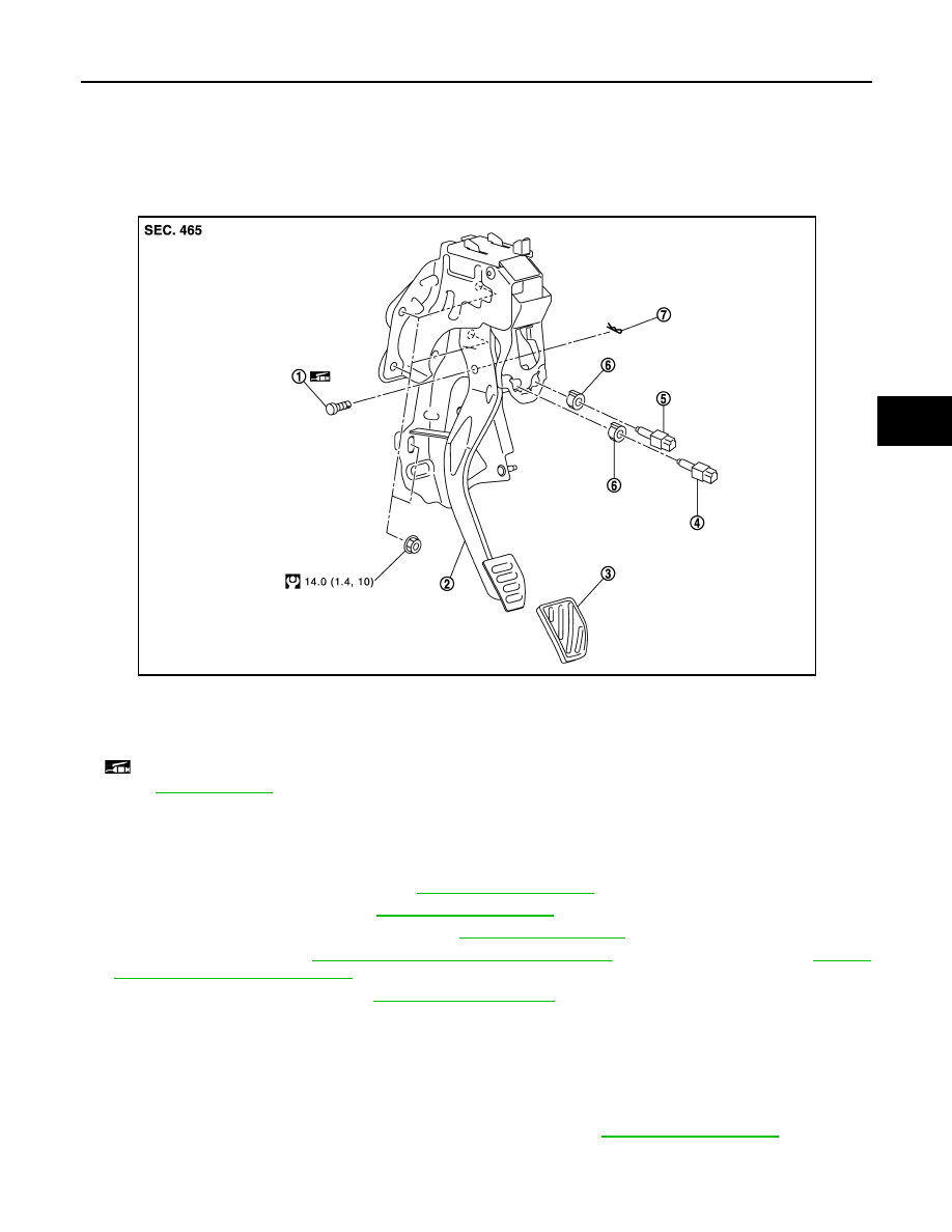
Exploded View
INFOID:0000000000925787
Removal and Installation
INFOID:0000000000925788
REMOVAL
1.
Remove front kicking plate inner. Refer to
2.
Remove dash side finisher. Refer to
3.
Remove instrument driver lower panel. Refer to
4.
Remove foot duct. Refer to
VTL-47, "FOOT DUCTS : Exploded View"
(automatic air conditioner),
(manual air conditioner)
5.
Remove mode door motor. Refer to
(automatic air conditioner).
6.
Disconnect ASCD cancel switch and the stop lamp switch harness connectors.
7.
Disconnect accelerator pedal position sensor harness connector.
8.
Remove steering member stay.
9.
Remove snap pin and clevis pin from clevis of brake booster.
10. Remove the brake pedal assembly and the accelerator pedal.
11. Remove the accelerator pedal from brake pedal assembly. Refer to
INSTALLATION
Note the following, and installation is the reverse order of removal.
1.
Clevis pin
2.
Brake pedal assembly
3.
Brake pedal pad
4.
ASCD cancel switch
5.
Stop lamp switch
6.
Clip
7.
Snap pin
: Apply multi-purpose grease.
Refer to
for symbols not described on the above.
JPFIA0072GB
BR-18
< ON-VEHICLE REPAIR >
[LHD]
BRAKE PEDAL
• Apply the multi-purpose grease to the clevis pin and the mating faces. (Not necessary if grease has been
already applied.)
NOTE:
The clevis pin may be inserted in either direction.
Inspection and Adjustment
INFOID:0000000000925789
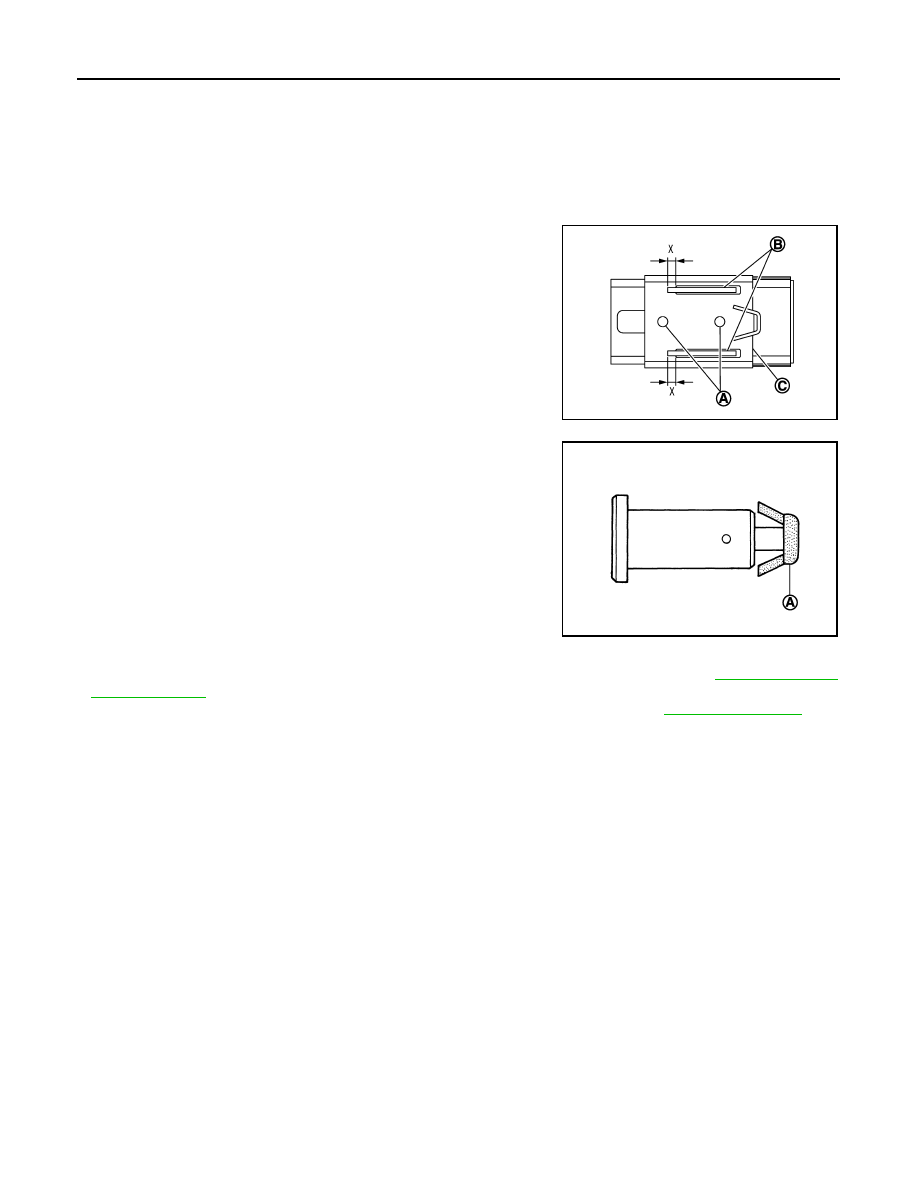
INSPECTION AFTER REMOVAL
• Check the following items and replace the brake pedal assembly if
necessary.
- Check the brake pedal upper rivet (A) for deformation.
- Check the brake pedal for bend, damage, and cracks on the
welded parts.
- Check the lapping length (X) of sub-bracket (B) and slide plate (C).
• Check clevis pin and plastic stopper (A) for damage and deforma-
tion. If any is found, replace clevis pin.
ADJUSTMENT AFTER INSTALLATION
• Perform the brake pedal adjustment after installing the brake pedal assembly. Refer to
• Perform the accelerator pedal check after installing the accelerator pedal. Refer to
.
Limit
Lapping length
: 5.0 mm (0.197 in)
PFIA0755J
PFIA0756J
Нет комментариевНе стесняйтесь поделиться с нами вашим ценным мнением.
Текст