Nissan Qashqai (2007-2010). Manual — part 1917

WCS-14
< FUNCTION DIAGNOSIS >
DIAGNOSIS SYSTEM (METER)
TURN IND
[On/Off]
Status of turn indicator lamp judged from turn indicator signal received from BCM
with CAN communication line.
FR FOG IND
[On/Off]
Status of front fog light indicator lamp judged from front fog light request signal
received from BCM with CAN communication line.
RR FOG IND
[On/Off]
Status of rear fog light indicator lamp judged from rear fog light request signal re-
ceived from BCM with CAN communication line.
OIL W/L
[On/Off]
Status of oil pressure warning lamp judged from oil pressure switch signal re-
ceived from IPDM E/R with CAN communication line.
LIGHT IND
[On/Off]
Status of light indicator lamp judged from position light request signal received
from BCM with CAN communication line.
DPF W/L
[On/Off]
DPF warning lamp status judged by the DPF warning lamp signal received from
ECM with the CAN communication line.
VDC/TCS IND
[On/Off]
Status of VDC indicator lamp judged from VDC OFF indicator lamp signal re-
ceived from ABS actuator and electric unit (control unit) with CAN communication
line.
ABS W/L
[On/Off]
Status of ABS warning lamp judged from ABS warning lamp signal received from
ABS actuator and electric unit (control unit) with CAN communication line.
SLIP IND
[On/Off]
Status of slip indicator lamp judged from slip indicator lamp signal received from
ABS actuator and electric unit (control unit) with CAN communication line.
BRAKE W/L
[On/Off]
Status of brake warning lamp judged from brake warning lamp signal received
from ABS actuator and electric unit (control unit) with CAN communication line.
NOTE:
Displays “Off” if the brake warning lamp is illuminated when the valve check
starts, the parking brake switch is turned ON or the brake fluid level switch is
turned ON.
OIL LEVEL IND
[LEVEL1, 2, 3, 4, 5/CR NG/On]
Oil level status judged by the oil level sensor signal from the oil level sensor.
KEY G W/L
[On/Off]
Status of key warning lamp (G) judged from key warning signal received from
BCM with CAN communication line.
KEY R W/L
[On/Off]
Status of key warning lamp (R) judged from key warning signal received from
BCM with CAN communication line.
KEY KNOB W/L
[On/Off]
Key knob switch status received from Intelligent Key unit with the CAN commu-
nication line.
M RANGE SW
[On/Off]
X
Status of mode select switch (manual).
NM RANGE SW
[On/Off]
X
Status of mode select switch (auto).
AT SFT UP SW
[On/Off]
X
Status of position select switch (up).
AT SFT DWN SW
[On/Off]
X
Status of position select switch (down).
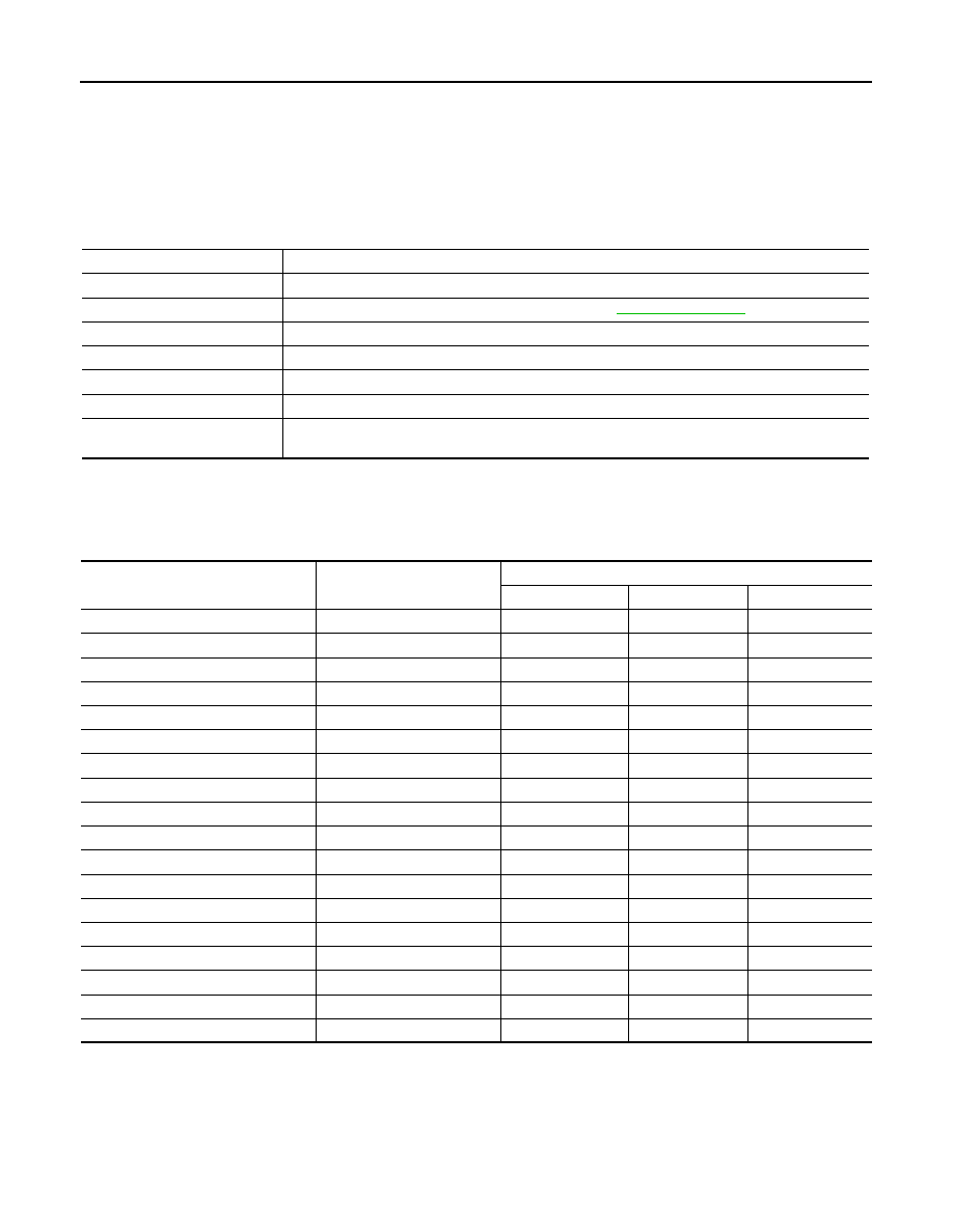
Display item [Unit]
MAIN
SIGNALS
Description

WCS
DIAGNOSIS SYSTEM (METER)
WCS-15
< FUNCTION DIAGNOSIS >
C
D
E
F
G
H
I
J
K
L
M
B
A
O
P
NOTE:
Some items are not available according to vehicle specification.
P RANGE IND
[On/Off]
X
Status of shift position indicator judged from shift position signal and manual
mode indicator signal received from TCM with CAN communication line.
R RANGE IND
[On/Off]
X
N RANGE IND
[On/Off]
X
D RANGE IND
[On/Off]
X
4 RANGE IND
[On/Off]
X
3 RANGE IND
[On/Off]
X
2 RANGE IND
[On/Off]
X
AT CHECK W/L
[On/Off]
A/T check warning lamp status judged by the A/T CHECK indicator lamp signal
received from TCM with the CAN communication line.
CVT IND
[On/Off]
CVT indicator lamp status judged from CVT CHECK indicator lamp signal re-
ceived from TMC with the CAN communication line.
CRUISE IND
[On/Off]
Status of CRUISE indicator judged from ASCD CRUISE lamp signal received
from ECM with CAN communication line.
SET IND
[On/Off]
Status of set indicator judged from ASCD SET indicator signal received from
ECM with CAN communication line.
4WD LOCK SW
[On/Off]
4WD lock switch status judged by the 4WD signal received from 4WD control unit
with the CAN communication line.
4WD LOCK IND
[On/Off]
4WD lock indicator status judged by the 4WD signal received from 4WD control
unit with the CAN communication line.
4WD W/L
[On/Off]
Status of 4WD warning lamp judged from 4WD warning lamp signal received
from 4WD control unit with CAN communication line.
Display item [Unit]
MAIN
SIGNALS
Description
WCS-16
< FUNCTION DIAGNOSIS >
DIAGNOSIS SYSTEM (BCM)
DIAGNOSIS SYSTEM (BCM)
COMMON ITEM
COMMON ITEM : CONSULT-III Function (BCM - COMMON ITEM)
INFOID:0000000001102445
APPLICATION ITEM
CONSULT-III performs the following functions via CAN communication with BCM.
SYSTEM APPLICATION
BCM can perform the following functions for each system.
NOTE:
It can perform the diagnosis modes except the following for all sub system selection items.
BUZZER
BUZZER : CONSULT-III Function (BCM - BUZZER)
INFOID:0000000000892413
CONSULT-III FUNCTION (BCM – BUZZER)
Diagnosis mode
Function Description
WORK SUPPORT
Changes the setting for each system function.
SELF-DIAG RESULTS
Displays the diagnosis results judged by BCM. Refer to
CAN DIAG SUPPORT MNTR
Monitors the reception status of CAN communication viewed from BCM.
DATA MONITOR
The BCM input/output signals are displayed.
ACTIVE TEST
The signals used to activate each device are forcibly supplied from BCM.
ECU IDENTIFICATION
The BCM part number is displayed.
CONFIGURATION
• Enables to read and save the vehicle specification.
• Enables to write the vehicle specification when replacing BCM.
System
Sub system selection item
Diagnosis mode
WORK SUPPORT
DATA MONITOR
ACTIVE TEST
—
BCM
×
Door lock
DOOR LOCK
×
×
×
Rear window defogger
REAR DEFOGGER
×
×
Warning chime
BUZZER
×
×
Interior room lamp timer
INT LAMP
×
×
×
Remote keyless entry system
MULTI REMOTE ENT
×
×
×
Exterior lamp
HEAD LAMP
×
×
×
Wiper and washer
WIPER
×
×
×
Turn signal and hazard warning lamps
FLASHER
×
×
Air conditioner
AIR CONDITONER
×
Intelligent Key system
INTELLIGENT KEY
×
Combination switch
COMB SW
×
Immobilizer
IMMU
×
×
Interior room lamp battery saver
BATTERY SAVER
×
×
×
Trunk open
TRUNK
×
Vehicle security system
THEFT ALM
×
×
×
Signal buffer system
SIGNAL BUFFER
×
×
PTC heater system
PTC HEATER
×
×

WCS
DIAGNOSIS SYSTEM (BCM)
WCS-17
< FUNCTION DIAGNOSIS >
C
D
E
F
G
H
I
J
K
L
M
B
A
O
P
DATA MONITOR
ACTIVE TEST
Test item
Diagnosis mode
Description
Buzzer
Data Monitor
Displays BCM input data in real time.
Active Test
Operation of electrical loads can be checked by sending driving signal to them.
Display item
[Unit]
Description
IGN ON SW
[On/Off]
Ignition switch (ON) status judged by ignition power supply input.
KEY ON SW
[On/Off]
Key switch status.
DOOR SW -DR
[On/Off]
Front door switch (driver side) status judged by BCM.
TAIL LAMP SW
[On/Off]
Lighting switch status judged by the lighting switch signal read with combination switch reading func-
tion.
BUCKLE SW
[On/Off]
Seat belt buckle switch status judged by the seat belt buckle switch signal received from combination
meter via CAN communication.
DOOR SW -AS
Front door switch (passenger side) status judged by BCM.
DOOR SW -RR
Rear door switch RH status judged by BCM.
DOOR SW -RL
Rear door switch LH status judged by BCM.
BACK DOOR SW
Back door switch status judged by BCM.
VEHICLE SPEED
[km/h]
Vehicle speed signal value received from combination meter via CAN communication.
Display item
Description
LIGHT WARN ALM
The light reminder warning operation can be checked by operating the relevant function (On/Off).
IGN KEY WARN ALM
The key warning operation can be checked by operating the relevant function (On/Off).
KEY REMINDER WARN
The key reminder warning operation can be checked by operating the relevant function (On/Off).
Нет комментариевНе стесняйтесь поделиться с нами вашим ценным мнением.
Текст