Nissan Qashqai (2007-2010). Manual — part 608

DIAGNOSIS AND REPAIR WORKFLOW
DLN-5
< BASIC INSPECTION >
[TRANSFER: TY30A]
C
E
F
G
H
I
J
K
L
M
A
B
DLN
N
O
P
BASIC INSPECTION
DIAGNOSIS AND REPAIR WORKFLOW
Work Flow
INFOID:0000000000972071
DETAILED FLOW
1.
INTERVIEW FROM THE CUSTOMER
Clarify customer complaints before inspection. First of all, reproduce symptoms, and understand them fully.
Ask customer about his/her complaints carefully. Check symptoms by driving vehicle with customer, if neces-
sary.
CAUTION:
Customers are not professional. Never guess easily like “maybe the customer means that...,” or
“maybe the customer mentions this symptom”.
>> GO TO 2.
2.
CHECK 4WD WARNING LAMP
Start engine and drive at 30 km/h (19 MPH) or more for approx. 1 minute.
Is 4WD warning lamp illuminated?
YES
>> GO TO 3.
NO
>> GO TO 6.
3.
PERFORM SELF-DIAGNOSIS
With CONSULT-III
1.
Perform 4WD control unit self-diagnosis.
2.
Perform malfunction detected by self-diagnosis.
3.
Erase 4WD control unit self-diagnosis results.
>> GO TO 4.
4.
CHECK TERMINALS AND HARNESS CONNECTORS
Check pin terminals for damage or loose connection with harness connector.
>> GO TO 5.
5.
CHECK SYMPTOM REPRODUCTION
With CONSULT-III
Perform DTC reproduction procedure for the error system.
Is any error detected?
YES
>> GO TO 2.
NO
>> GO TO 6.
6.
PERFORM SYMPTOM DIAGNOSIS
Perform the symptom diagnosis for each system.
Is any malfunction present?
YES
>> GO TO 2.
NO
>> GO TO 7.
7.
FINAL CHECK
With CONSULT-III
Check input/output signal standard of 4WD control unit.
Is the input/output the standard value?
YES
>> INSPECTION END
NO
>> GO TO 2.
DLN-6
< FUNCTION DIAGNOSIS >
[TRANSFER: TY30A]
4WD SYSTEM
FUNCTION DIAGNOSIS
4WD SYSTEM
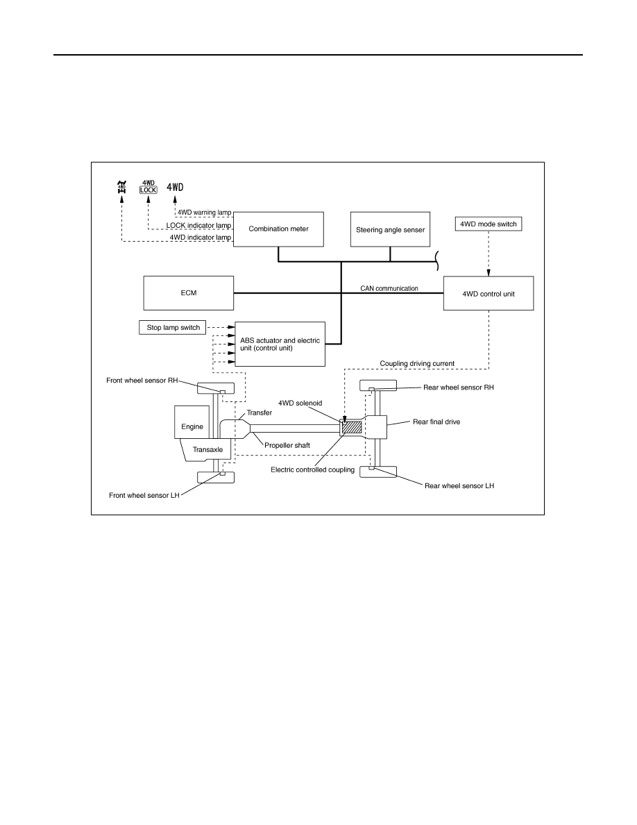
System Diagram
INFOID:0000000000972072
CONTROL DIAGRAM
CROSS-SECTIONAL VIEW
JSDIA0204GB

4WD SYSTEM
DLN-7
< FUNCTION DIAGNOSIS >
[TRANSFER: TY30A]
C
E
F
G
H
I
J
K
L
M
A
B
DLN
N
O
P
M/T models
CVT models
JSDIA0206ZZ
1.
Transfer case
2.
Adapter case
3.
Ring gear shaft
4.
Ring gear
5.
Companion flange
6.
Drive pinion
JSDIA0205ZZ
1.
Transfer case
2.
Adapter case
3.
Ring gear shaft
4.
Ring gear
5.
Companion flange
6.
Drive pinion
DLN-8
< FUNCTION DIAGNOSIS >
[TRANSFER: TY30A]
4WD SYSTEM
System Description
INFOID:0000000000972073
DESCRIPTION
• 4WD controls distribution of drive power between front-wheel drive (100:0) and 4WD (50:50) conditions
according to signals from sensors.
• It transmits/receives each signal from the following control unit via CAN communication line.
AUTO Mode
• Electronic control allows optimal distribution of torque to front/rear wheels to match road conditions.
• 4WD mode makes possible stable driving, with no wheel spin, on snowy roads or other slippery surfaces.
• On roads which do not require 4WD, AUTO mode contributes to improved fuel economy by driving in condi-
tions close to front-wheel drive.
• Sensor inputs determine the vehicle's turning condition, and tight cornering/braking are controlled by distrib-
uting optimum torque to rear wheels.
LOCK Mode
• Front/rear wheel torque distribution is fixed, ensuring stable driving when climbing slopes.
• Vehicle will switch automatically to AUTO mode if vehicle speed increases. If vehicle speed then decreases,
the vehicle automatically returns to direct 4-wheel driving conditions.
• LOCK mode will change to AUTO mode automatically, when the vehicle speed exceeds approx. 10 km/h (6
MPH). The LOCK indicator light keeps illuminating.
NOTE:
If there is a significant difference in pressure or wear between tires, full vehicle performance is not available.
LOCK mode may be prohibited, or speeds at which LOCK mode is enabled may be restricted detecting tire
conditions.
2WD Mode
Vehicle is in front-wheel drive.
NOTE:
If front wheels are slipping in 2WD mode, do not switch to AUTO or LOCK. This can cause difficulties for the
system.
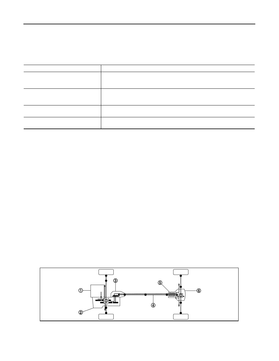
POWER TRANSFER DIAGRAM
OPERATION PRINCIPLE
Component parts
Function
ABS actuator and electric unit (control unit)
Transmits the following signals via CAN communication to 4WD control unit.
• Vehicle speed signal
• Stop lamp switch signal (brake signal)
ECM
Transmits the following signals via CAN communication to 4WD control unit.
• Accelerator pedal position signal
• Engine speed signal
Combination meter
Transmits conditions of parking brake switch signal via CAN communication to 4WD con-
trol unit.
Steering angle sensor
Transmits conditions of steering angle sensor signal via CAN communication to 4WD
control unit.
1.
Engine
2.
Transaxle
3.
Transfer
4.
Propeller shaft
5.
Electric controlled coupling
6.
Rear final drive
JSDIA0208ZZ
Нет комментариевНе стесняйтесь поделиться с нами вашим ценным мнением.
Текст