Nissan Qashqai (2007-2010). Manual — part 573
P0705 PARK/NEUTRAL POSITION SWITCH
TM-227
< COMPONENT DIAGNOSIS >
[CVT: RE0F10A]
C
E
F
G
H
I
J
K
L
M
A
B
TM
N
O
P
Diagnosis Procedure
INFOID:0000000000988655
1.
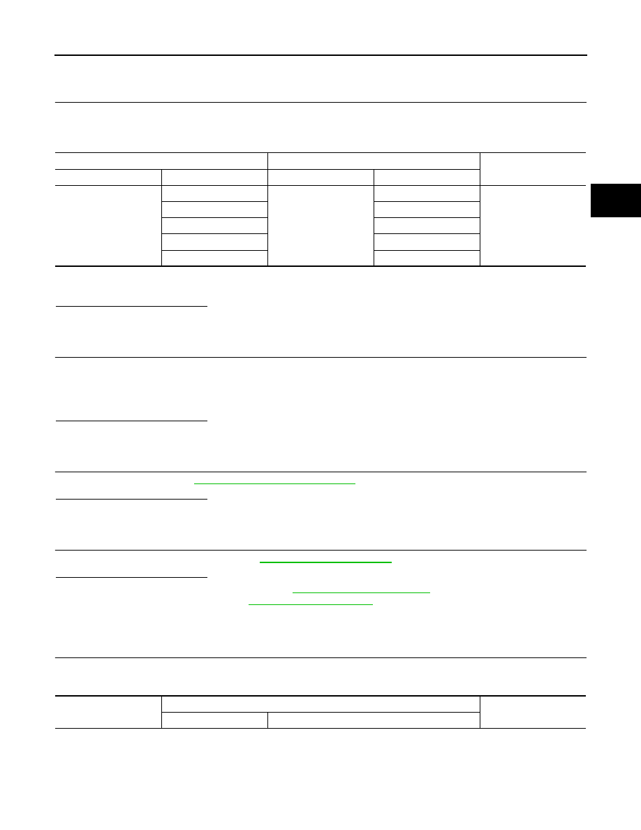
CHECK HARNESS BETWEEN TCM AND PNP SWITCH
1.
Turn ignition switch OFF.
2.
Disconnect TCM connector and PNP switch connector.
3.
Check continuity between TCM connector terminals and PNP switch connector terminals.
4.
If OK, check harness for short to ground and short to power.
5.
Reinstall any part removed.
Is the inspection result normal?
OK
>> GO TO 2.
NG
>> Repair or replace damaged parts.
2.
DETECT MALFUNCTIONING ITEM
Check the following items.
• Harness for short or open between ignition switch and PNP switch.
• 10A fuse (No. 55, located in the IPDM E/R).
• Ignition switch.
Is the inspection result normal?
OK
>> GO TO 3.
NG
>> Repair or replace damaged parts.
3.
CHECK PNP SWITCH
Check PNP switch. Refer to
TM-227, "Component Inspection"
.
Is the inspection result normal?
OK
>> GO TO 4.
NG
>> Repair or replace damaged parts.
4.
CHECK TCM
Check TCM input/output signals. Refer to
.
Is the inspection result normal?
OK
>> Check intermittent incident. Refer to
GI-39, "Intermittent Incident"
.
NG
Component Inspection
INFOID:0000000000988656
1.
CHECK PNP SWITCH
Change selector lever to various positions to check the continuity between terminals on the PNP switch and
ground.
TCM connector
PNP switch connector
Continuity
Connector
Terminal
Connector
Terminal
F25
1
F21
8
Existed
2
3
3
4
4
1
11
2
Selector lever position
PNP switch connector
Continuity
Connector
Terminal

TM-228
< COMPONENT DIAGNOSIS >
[CVT: RE0F10A]
P0705 PARK/NEUTRAL POSITION SWITCH
Is the inspection result normal?
YES
>> INSPECTION END
NO
>> GO TO 2.
2.
CHECK CVT POSITION
1.
Disconnect control cable.
2.
Check PNP switch. (Refer to step 1 above.)
Is the inspection result normal?
YES
>> Adjust CVT position. Refer to
TM-324, "Inspection and Adjustment"
.
NO
>> GO TO 3.
3.
CHECK PNP SWITCH
1.
Remove PNP switch from transaxle assembly. Refer to
2.
Check PNP switch. (Refer to step 1 above.)
Is the inspection result normal?
YES
>> Adjust PNP switch. Refer to
TM-337, "Inspection and Adjustment"
.
NO
>> Replace PNP switch. Refer to
P
F21
2
5
Existed
6
7
R
5
8
N
3
5
6
7
D
4
5
P0710 CVT FLUID TEMPERATURE SENSOR
TM-229
< COMPONENT DIAGNOSIS >
[CVT: RE0F10A]
C
E
F
G
H
I
J
K
L
M
A
B
TM
N
O
P
P0710 CVT FLUID TEMPERATURE SENSOR
Description
INFOID:0000000000988657
The CVT fluid temperature sensor detects the CVT fluid temperature and sends a signal to the TCM.
DTC Logic
INFOID:0000000000988658
DTC DETECTION LOGIC
DTC CONFIRMATION PROCEDURE
CAUTION:
Always drive vehicle at a safe speed.
NOTE:
If “DTC CONFIRMATION PROCEDURE” has been previously performed, always turn ignition switch
OFF and wait at least 10 seconds before performing the next test.
After the repair, perform the following procedure to confirm the malfunction is eliminated.
1.
CHECK DTC DETECTION
With CONSULT-III
1.
Turn ignition switch ON.
2.
Select “DATA MONITOR”.
3.
Start engine and maintain the following conditions for at least 10 minutes (Total).
With GST
Follow the procedure “With CONSULT-III”.
Is “P0710 ATF TEMP SEN/CIRC” detected?
YES
>> Go to
NO
>> Check intermittent incident. Refer to
GI-39, "Intermittent Incident"
.
Diagnosis Procedure
INFOID:0000000000988659
1.
CHECK CVT FLUID TEMPERATURE SENSOR CIRCUIT
1.
Turn ignition switch OFF.
2.
Disconnect the TCM connector.
3.
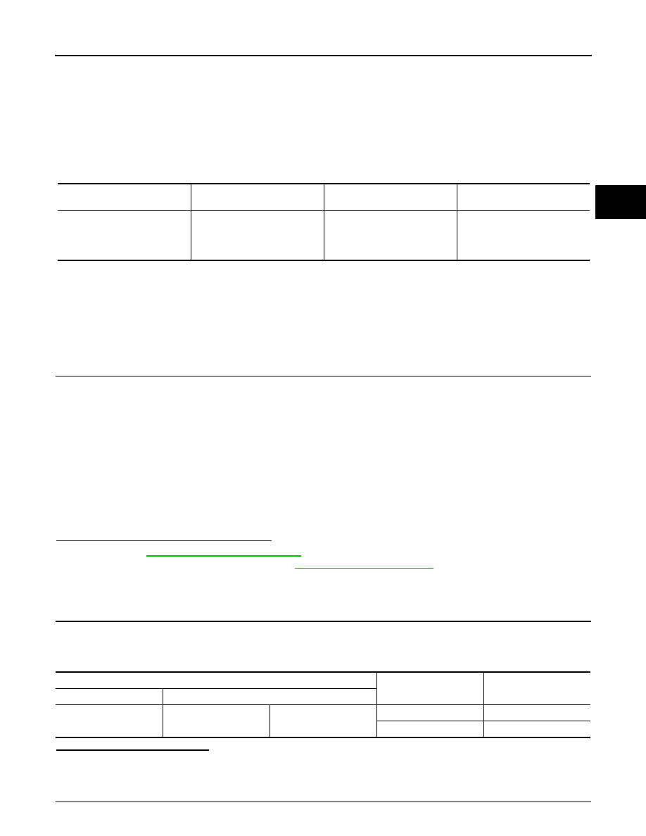
Check resistance between TCM connector terminals.
Is the inspection result normal?
YES
>> GO TO 4.
NO
>> GO TO 2.
2.
CHECK CVT FLUID TEMPERATURE SENSOR
DTC
Item
(CONSULT-III screen term)
Malfunction is detected when...
Possible cause
P0710
ATF TEMP SEN/CIRC
During running, the CVT fluid
temperature sensor signal volt-
age is excessively high or low.
• Harness or connectors
(Sensor circuit is open or
shorted.)
• CVT fluid temperature sensor
VEHICLE SPEED
: 10 km/h (6 MPH) or more
ENG SPEED
: 450 rpm more than
ACC PEDAL OPEN
: More than 1.0/8
RANGE
: “D” position
TCM connector
Temperature
°
C (
°
F)
Resistance (Approx.)
Connector
Terminal
F25
13
25
20 (68)
6.5 k
Ω
80 (176)
0.9 k
Ω

TM-230
< COMPONENT DIAGNOSIS >
[CVT: RE0F10A]
P0710 CVT FLUID TEMPERATURE SENSOR
Check CVT fluid temperature sensor. Refer to
TM-230, "Component Inspection"
.
Is the inspection result normal?
YES
>> GO TO 3.
NO
>> Replace the transaxle assembly. Refer to
(4WD).
3.
CHECK HARNESS BETWEEN TCM AND CVT FLUID TEMPERATURE SENSOR
1.
Disconnect the CVT unit harness connector.
2.
Check continuity between TCM connector terminals and CVT unit harness connector terminals.
3.
If OK, check harness for short to ground and short to power.
4.
Reinstall any part removed.
Is the inspection result normal?
OK
>> GO TO 4.
NG
>> Repair or replace damaged parts.
4.
CHECK TCM
Check TCM input/output signals. Refer to
.
Is the inspection result normal?
YES
>> Check intermittent incident. Refer to
GI-39, "Intermittent Incident"
.
NO
Component Inspection
INFOID:0000000000988660
CVT FLUID TEMPERATURE SENSOR
1.
CHECK CVT FLUID TEMPERATURE SENSOR
1.
Turn ignition switch OFF.
2.
Disconnect CVT unit harness connector.
3.
Check resistance between CVT unit harness connector terminals.
Is the inspection result normal?
YES
>> INSPECTION END
NO
>> Replace the transaxle assembly. Refer to
(4WD).
TCM connector
CVT unit harness connector
Continuity
Connector
Terminal
Connector
Terminal
F25
13
F24
17
Existed
25
19
CVT unit harness connector
Temperature
°
C (
°
F)
Resistance (Approx.)
Connector
Terminal
F24
17
19
20 (68)
6.5 k
Ω
80 (176)
0.9 k
Ω
Нет комментариевНе стесняйтесь поделиться с нами вашим ценным мнением.
Текст