Nissan Qashqai (2007-2010). Manual — part 559
REVERSE IDLER SHAFT AND GEAR
TM-171
< DISASSEMBLY AND ASSEMBLY >
[6MT: RS6F52A]
C
E
F
G
H
I
J
K
L
M
A
B
TM
N
O
P
REVERSE IDLER SHAFT AND GEAR
Exploded View
INFOID:0000000001034963
Disassembly
INFOID:0000000001034964
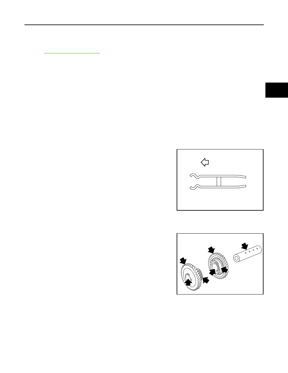
1.
Remove reverse idler gear (rear), reverse coupling sleeve, and reverse insert springs simultaneously.
2.
Remove reverse idler gear needle bearing.
3.
Remove thrust needle bearing.
4.
Remove reverse baulk ring.
5.
Remove reverse idler gear (front).
6.
Remove reverse idler gear needle bearing.
7.
Remove thrust needle bearing.
8.
Remove retaining pin from reverse idler shaft.
Assembly
INFOID:0000000001034965
Note the following, and assemble in the reverse order of disassembly.
CAUTION:
• Be careful with orientation of reverse insert spring.
• Never reuse retaining pin.
Inspection
INFOID:0000000001034966
REVERSE IDLER SHAFT AND GEAR
Check items below. If necessary, replace them with new ones.
• Damage, peeling, dent, uneven wear, bending, and other non-
standard conditions of the shaft.
• Excessive wear, damage, peeling, and other non-standard condi-
tions of the gears.
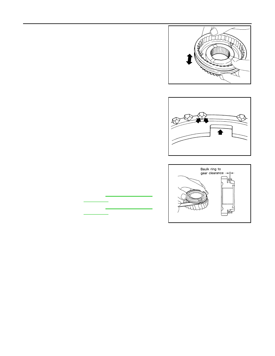
SYNCHRONIZER
Synchronizer Hub and Coupling Sleeve
: Front
PCIB1924E
SCIA0953J
TM-172
< DISASSEMBLY AND ASSEMBLY >
[6MT: RS6F52A]
REVERSE IDLER SHAFT AND GEAR
Check items below. If necessary, replace them with new ones.
• Damage and unusual wear on contact surfaces of coupling sleeve,
synchronizer hub of reverse idler gear (rear), and insert spring.
• Coupling sleeve and synchronizer hub of reverse idler gear (rear)
must move smoothly.
Baulk Ring
Check damage, or excessive wear on cam face of baulk ring or
working face of insert. If necessary, replace it with new ones.
Baulk Ring Clearance for Single Cone Synchronizer (Reverse)
Push baulk ring on the cone and measure the clearance between
baulk ring and cone. If the measurement is below limit, replace it with
a new one.
BEARING
Check items below. If necessary, replace them with new ones.
• Damage and rough rotation of bearing
SMT637A
SMT867D
Clearance
Standard value
: Refer to
Limit value
: Refer to
SMT140
FINAL DRIVE
TM-173
< DISASSEMBLY AND ASSEMBLY >
[6MT: RS6F52A]
C
E
F
G
H
I
J
K
L
M
A
B
TM
N
O
P
FINAL DRIVE
Exploded View
INFOID:0000000001034967
Disassembly
INFOID:0000000001034968
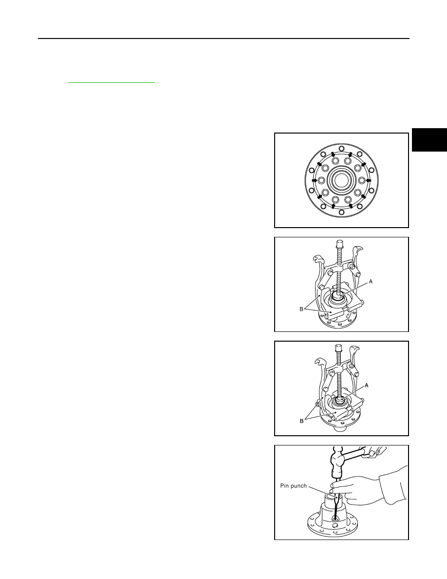
DIFFERENTIAL CASE
1.
Remove final gear mounting bolts and then separate the final gear from differential case.
2.
Remove reduction gear mounting bolts.
3.
Remove differential side bearing (clutch housing side) using the
drift (A) [SST: ST33061000] and pullers (B).
CAUTION:
Hook a puller on the inner race of differential side bearing.
4.
Remove reduction gear.
5.
Remove differential side bearing (transaxle case side) using the
drift (A) [SST: ST33061000] and pullers (B).
CAUTION:
Hook a puller on the inner race of differential side bearing.
6.
Remove retaining pin from differential case using a pin punch
and then remove pinion mate shaft.
7.
Rotate pinion mate gears and remove pinion mate gears, pinion
mate thrust washers, side gears, and side gear thrust washers
from differential case.
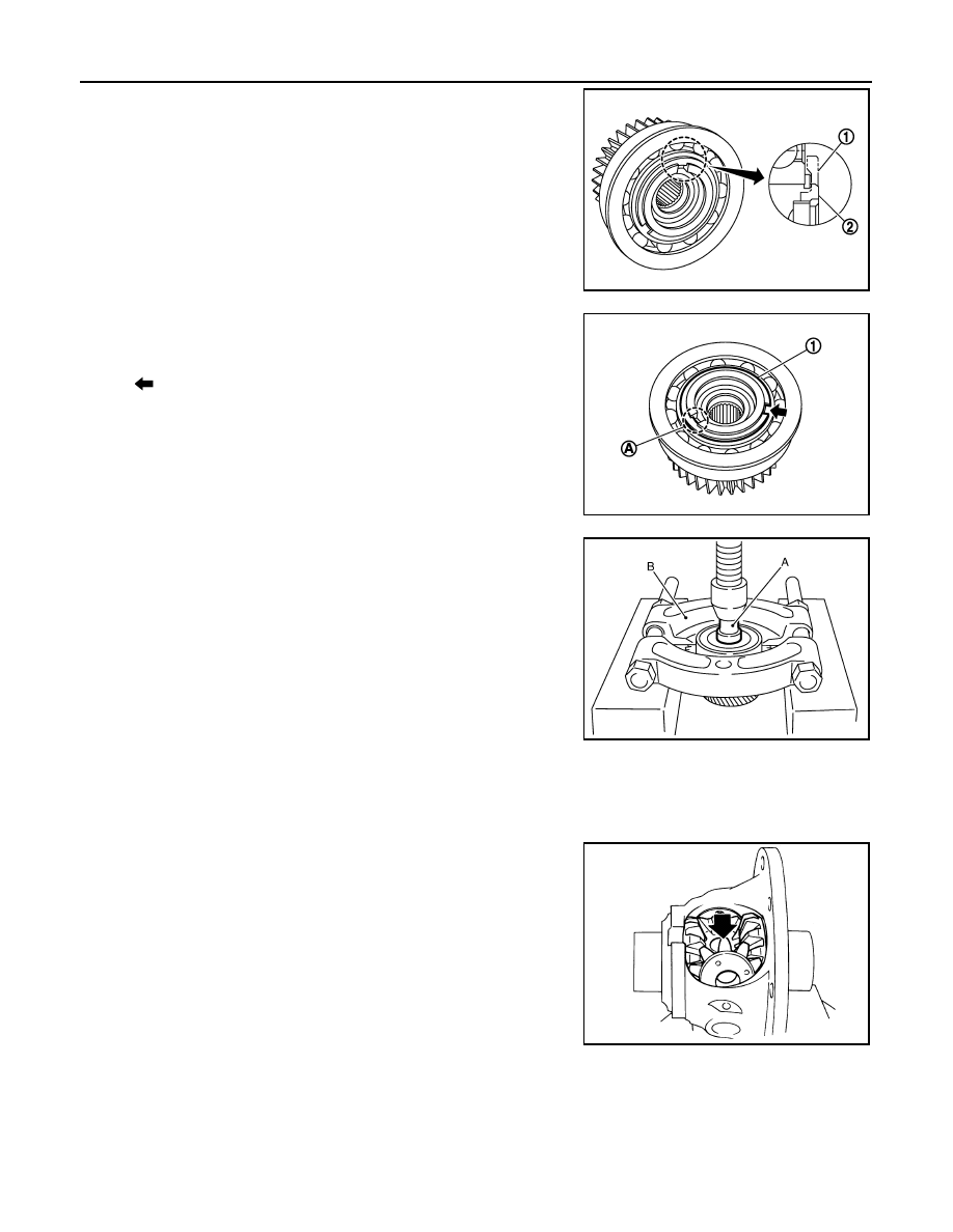
OUTPUT GEAR
JPDIC0036ZZ
PCIB1876E
JPDIC0103ZZ
SCIA0908E
TM-174
< DISASSEMBLY AND ASSEMBLY >
[6MT: RS6F52A]
FINAL DRIVE
1.
Remove snap ring (1).
2.
Remove snap ring (1).
3.
Remove output gear bearing using the drift (A) [SST:
ST30612000] and a puller (B).
Assembly
INFOID:0000000001034969
DIFFERENTIAL CASE
1.
Apply gear oil to sliding area of differential case, each gear, and thrust washer.
2.
Install side gear thrust washers and side gears into differential
case.
3.
While rotating pinion mate thrust washers and pinion mate
gears, aligning them diagonally, install them into differential
case.
2
: Output gear
JPDIC0104ZZ
A
: Output gear groove
: Snap ring notch
JPDIC0040ZZ
JPDIC0038ZZ
SMT839
Нет комментариевНе стесняйтесь поделиться с нами вашим ценным мнением.
Текст