Nissan Qashqai (2007-2010). Manual — part 388
U1010 CONTROL UNIT (CAN)
EC-1071
< COMPONENT DIAGNOSIS >
[MR20DE (WITHOUT EURO-OBD)]
C
D
E
F
G
H
I
J
K
L
M
A
EC
N
P
O
U1010 CONTROL UNIT (CAN)
Description
INFOID:0000000001094092
CAN (Controller Area Network) is a serial communication line for real time application. It is an on-vehicle mul-
tiplex communication line with high data communication speed and excellent error detection ability. Many elec-
tronic control units are equipped onto a vehicle, and each control unit shares information and links with other
control units during operation (not independent). In CAN communication, control units are connected with 2
communication lines (CAN H line, CAN L line) allowing a high rate of information transmission with less wiring.
Each control unit transmits/receives data but selectively reads required data only.
DTC Logic
INFOID:0000000001094093
DTC DETECTION LOGIC
DTC CONFIRMATION PROCEDURE
1.
PERFORM DTC CONFIRMATION PROCEDURE
1.
Turn ignition switch ON.
2.
Check DTC.
Is DTC detected?
YES
>> Go to
EC-1074, "Diagnosis Procedure"
NO
>> INSPECTION END
Diagnosis Procedure
INFOID:0000000001094094
1.
INSPECTION START
With CONSULT-III
1.
Turn ignition switch ON.
2.
Select “SELF-DIAG RESULTS” mode with CONSULT-III.
3.
Touch “ERASE”.
4.
Perform DTC CONFIRMATION PROCEDURE.
See
.
5.
Check DTC.
Without CONSULT-III
1.
Turn ignition switch ON.
2.
Erase the Diagnostic Test Mode II (Self-diagnostic results) memory.
3.
Perform DTC CONFIRMATION PROCEDURE.
See
.
4.
Check DTC.
Is the DTC U1010 displayed again?
YES
>> GO TO 2.
NO
>> INSPECTION END
2.
REPLACE ECM
1.
Replace ECM.
2.
EC-989, "ADDITIONAL SERVICE WHEN REPLACING CONTROL UNIT : Special Repair Require-
.
>> INSPECTION END
DTC No.
Trouble diagnosis name
DTC detecting condition
Possible cause
U1010
CAN communication bus
When detecting error during the initial diagno-
sis of CAN controller of ECM.
• ECM
EC-1072
< COMPONENT DIAGNOSIS >
[MR20DE (WITHOUT EURO-OBD)]
P0011 IVT CONTROL
P0011 IVT CONTROL
DTC Logic
INFOID:0000000001094095
DTC DETECTION LOGIC
NOTE:
If DTC P0011 is displayed with DTC P1111, first perform the trouble diagnosis for
.
DTC CONFIRMATION PROCEDURE
1.
PRECONDITIONING
If DTC Confirmation Procedure has been previously conducted, always turn ignition switch OFF and wait at
least 10 seconds before conducting the next test.
TESTING CONDITION:
Before performing the following procedure, confirm that battery voltage is between 10V and 16V at
idle.
Do you have CONSULT-III?
YES
>> GO TO 2.
NO
>> GO TO 4.
2.
PERFORM DTC CONFIRMATION PROCEDURE-I
With CONSULT-III
1.
Turn ignition switch ON and select “DATA MONITOR” mode with CONSULT-III.
2.
Start engine and warm it up to the normal operating temperature.
3.
Maintain the following conditions for at least 6 consecutive seconds. Hold the accelerator pedal as steady
as possible.
4.
Let engine idle for 10 seconds.
5.
Check 1st trip DTC.
Is 1st trip DTC detected?
YES
>> Go to
EC-1076, "Diagnosis Procedure"
NO
>> GO TO 3.
3.
PERFORM DTC CONFIRMATION PROCEDURE-II
With CONSULT-III
1.
Maintain the following conditions for at least 20 consecutive seconds.
DTC No.
Trouble diagnosis
name
Detecting condition
Possible cause
P0011
Intake valve timing
control performance
There is a gap between angle of target and
phase-control angle degree.
• Crankshaft position sensor (POS)
• Camshaft position sensor (PHASE)
• Intake valve control solenoid valve
• Accumulation of debris to the signal pick-up
portion of the camshaft
• Timing chain installation
• Foreign matter caught in the oil groove for in-
take valve timing control
ENG SPEED
1,200 - 2,000 rpm
COOLAN TEMP/S
More than 60
°
C (140
°
F)
B/FUEL SCHDL
More than 3.5 msec (CVT)
More than 4.2 msec (M/T)
Shift lever
P or N position (CVT)
N position (M/T)
ENG SPEED
2,000 - 3,175 rpm (A constant rotation is maintained.)
COOLAN TEMP/S
More than 70
°
C (221
°
F)
P0011 IVT CONTROL
EC-1073
< COMPONENT DIAGNOSIS >
[MR20DE (WITHOUT EURO-OBD)]
C
D
E
F
G
H
I
J
K
L
M
A
EC
N
P
O
CAUTION:
Always drive at a safe speed.
2.
Check 1st trip DTC.
Is 1st trip DTC detected?
YES
>> Go to
EC-1076, "Diagnosis Procedure"
NO
>> INSPECTION END
4.
PERFORM COMPONENT FUNCTION CHECK
Without CONSULT-III
1.
Start engine and warm it up to the normal operating temperature.
2.
Turn ignition switch OFF and wait at least 10 seconds.
3.
Start engine and let it idle.
4.
Check the voltage between ECM harness connector and ground under the following condition.
Is the inspection result normal?
YES
>> INSPECTION END
NO
>> Go to
EC-1076, "Diagnosis Procedure"
Diagnosis Procedure
INFOID:0000000001094096
1.
CHECK OIL PRESSURE WARNING LAMP
1.
Start engine.
2.
Check oil pressure warning lamp and confirm it is not illumi-
nated.
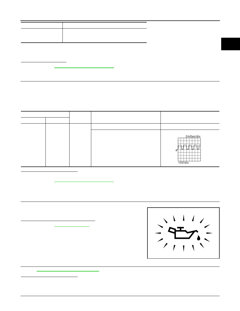
Is oil pressure warning lamp illuminated?
YES
>> Go to
.
NO
>> GO TO 2.
2.
CHECK INTAKE VALVE TIMING CONTROL SOLENOID VALVE
EC-1077, "Component Inspection"
.
Is the inspection result normal?
YES
>> GO TO 3.
NO
>> Replace intake valve timing control solenoid valve.
3.
CHECK CRANKSHAFT POSITION SENSOR (POS)
Shift lever
1st or 2nd position
Driving location uphill
Driving vehicle uphill
(Increased engine load will help maintain the driving
conditions required for this test.)
MAF sensor
Ground
Condition
Voltage
Connector
Terminal
E18
5
Ground
At idle
Battery voltage
When revving engine up to 2,000 rpm quickly
JMBIA0337GB
PBIA8559J
EC-1074
< COMPONENT DIAGNOSIS >
[MR20DE (WITHOUT EURO-OBD)]
P0011 IVT CONTROL
EC-812, "Component Inspection"
Is the inspection result normal?
YES
>> GO TO 4.
NO
>> Replace crankshaft position sensor (POS).
4.
CHECK CAMSHAFT POSITION SENSOR (PHASE)
EC-815, "Component Inspection"
Is the inspection result normal?
YES
>> GO TO 5.
NO
>> Replace camshaft position sensor (PHASE).
5.
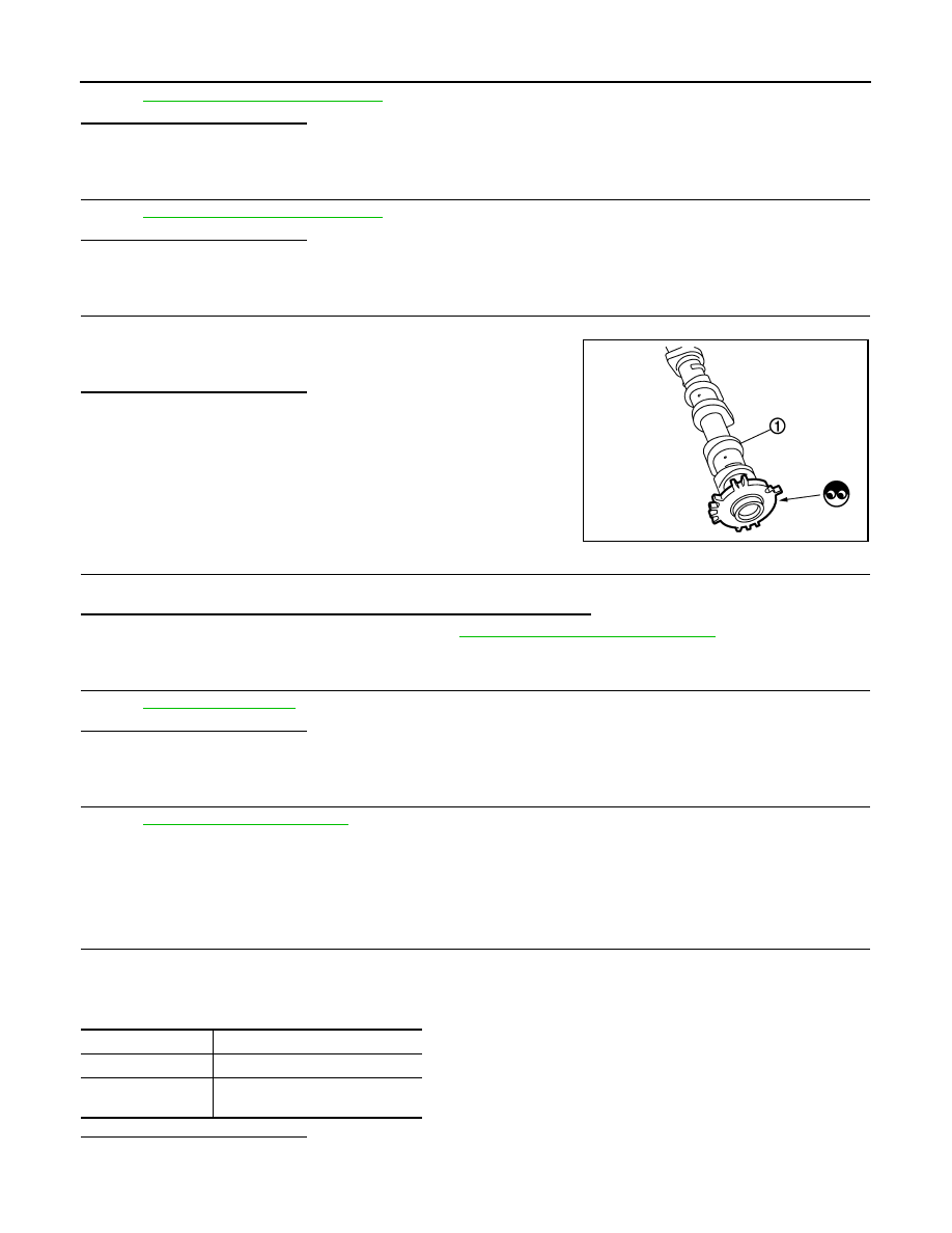
CHECK CAMSHAFT (INTAKE)
Check the following.
• Accumulation of debris to the signal plate of camshaft (1) rear end
• Chipping signal plate of camshaft rear end
Is the inspection result normal?
YES
>> GO TO 6.
NO
>> Remove debris and clean the signal plate of camshaft
rear end or replace camshaft.
6.
CHECK TIMING CHAIN INSTALLATION
Check service records for any recent repairs that may cause timing chain misaligned.
Are there any service records that may cause timing chain misaligned?
YES
>> Check timing chain installation. Refer to
EM-163, "Removal and Installation"
NO
>> GO TO 7.
7.
CHECK LUBRICATION CIRCUIT
Is the inspection result normal?
YES
>> GO TO 8.
NO
>> Clean lubrication line.
8.
CHECK INTERMITTENT INCIDENT
GI-39, "Intermittent Incident"
>> INSPECTION END
Component Inspection
INFOID:0000000001094097
1.
CHECK INTAKE VALVE TIMING CONTROL SOLENOID VALVE-I
1.
Turn ignition switch OFF.
2.
Disconnect intake valve timing control solenoid valve harness connector.
3.
Check resistance between intake valve timing control solenoid valve terminals as follows.
Is the inspection result normal?
YES
>> GO TO 2.
NO
>> Replace intake valve timing control solenoid valve.
PBIA9557J
Terminals
Resistance [at 20
°
C (68
°
F)]
1 and 2
6.7 - 7.7
Ω
1 or 2 and ground
∞
Ω
(Continuity should not exist)
Нет комментариевНе стесняйтесь поделиться с нами вашим ценным мнением.
Текст