Nissan Qashqai (2007-2010). Manual — part 19

EM-24
< ON-VEHICLE MAINTENANCE >
[HR16DE]
COMPRESSION PRESSURE
COMPRESSION PRESSURE
Inspection
INFOID:0000000000893835
1.
Warm up engine thoroughly. Then, stop it.
2.
Release fuel pressure. Refer to
.
3.
Remove ignition coil and spark plug from each cylinder. Refer to
.
4.
Connect an engine tachometer (not required in use of CONSULT-III).
5.
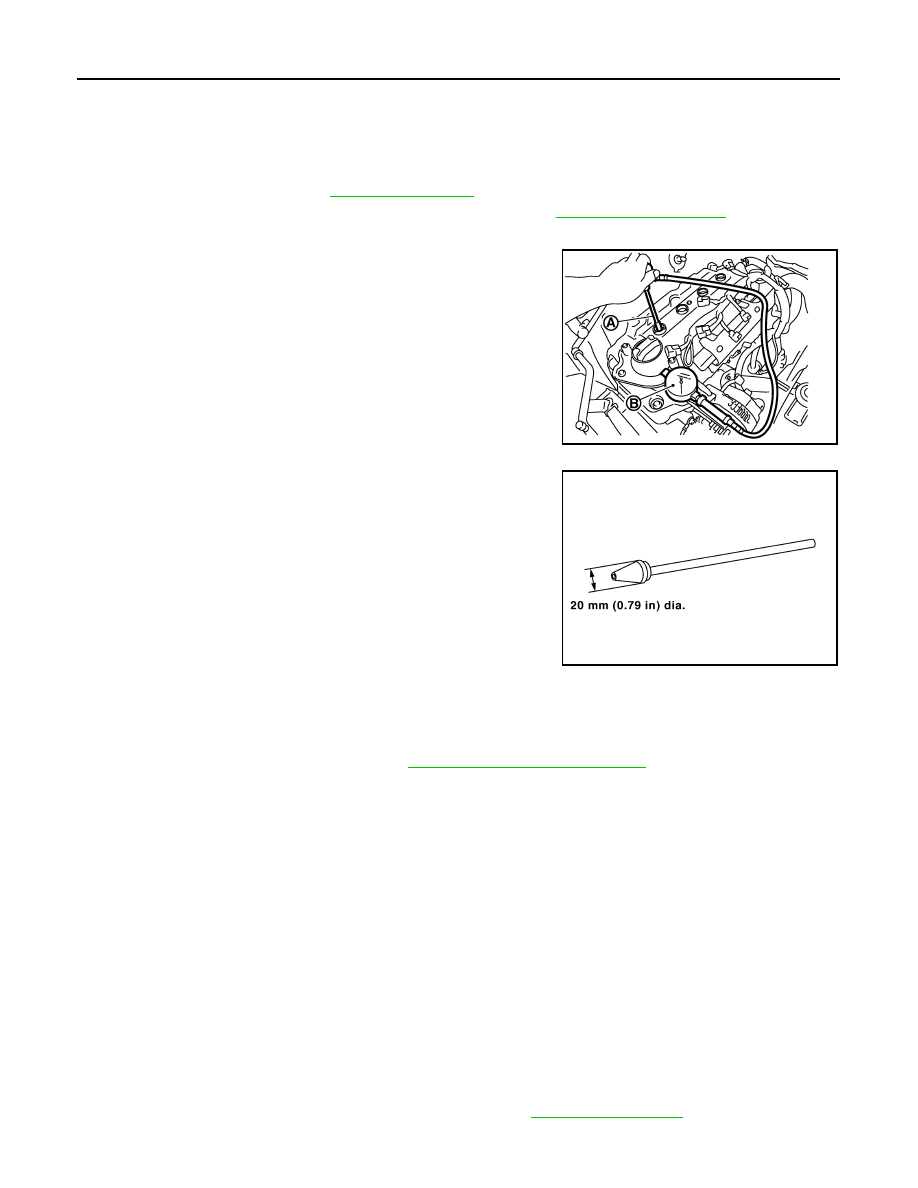
Install a compression tester (B) with an adapter (commercial
service tool) (A) onto spark plug hole.
• Use the adapter whose picking up end inserted to spark plug
hole is smaller than 20 mm (0.79 in) in diameter. Otherwise, it
may be caught by cylinder head during removal.
6.
With accelerator pedal fully depressed, turn ignition switch to “START” for cranking. When the gauge
pointer stabilizes, read the compression pressure and the engine rpm. Perform these steps to check each
cylinder.
CAUTION:
Always use fully a changed battery to obtain the specified engine speed.
• If the engine speed is out of the specified range, check battery liquid for proper gravity. Check engine
speed again with normal battery gravity.
• If compression pressure is below minimum value, check valve clearances and parts associated with
combustion chamber (Valve, valve seat, piston, piston ring, cylinder bore, cylinder head, cylinder head
gasket). After the checking, measure the compression pressure again.
• If some cylinder has low compression pressure, pour small amount of engine oil into the spark plug hole
of the cylinder to re-check it for compression.
- If the added engine oil improves the compression, piston rings may be worn out or damaged. Check pis-
ton rings and replace if necessary.
- If the compression pressure remains at low level despite the addition of engine oil, valves may be mal-
functioning. Check valves for damage. Replace valve or valve seat accordingly.
• If two adjacent cylinders have respectively low compression pressure and their compression remains
low even after the addition of engine oil, cylinder head gasket is leaking. In such a case, replace cylinder
head gasket.
7.
After inspection is completed, install removed parts.
8.
Start the engine, and confirm that the engine runs smoothly.
9.
Perform trouble diagnosis. If DTC appears, erase it. Refer to
PBIC3730E
SBIA0533E
Compression Pressure:
EM-115, "General Specification"
.

DRIVE BELT IDLER PULLEY
EM-25
< ON-VEHICLE REPAIR >
[HR16DE]
C
D
E
F
G
H
I
J
K
L
M
A
EM
N
P
O
ON-VEHICLE REPAIR
DRIVE BELT IDLER PULLEY
Exploded View
INFOID:0000000001093109
Removal and Installation
INFOID:0000000001093106
REMOVAL
1.
Remove drive belt. Refer to
EM-16, "Removal and Installation"
.
2.
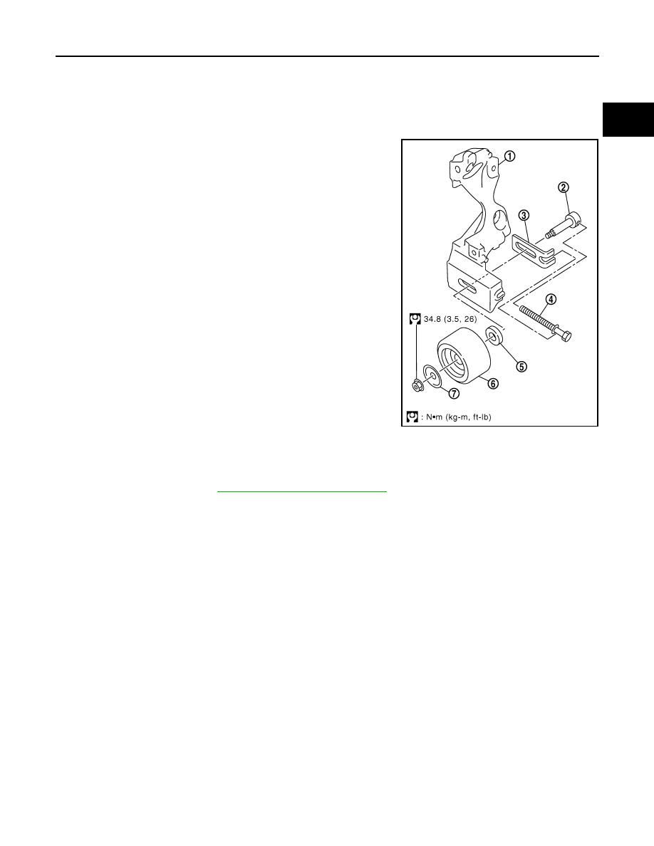
Remove the lock nut, and then remove the plate, idler pulley, and washer.
3.
Remove the center shaft together with the spacer with inserting the adjusting bolt.
INSTALLATION
1
: Alternator bracket
2
: Center shaft
3
: Spacer
4
: Adjusting bolt
5
: Washer
6
: Idler pulley
7
: Plate
PBIC3644E

EM-26
< ON-VEHICLE REPAIR >
[HR16DE]
DRIVE BELT IDLER PULLEY
1.
Insert the center shaft (1) into the slide groove of the spacer (2).
Fully screw in the adjusting bolt (3) in the belt loosening direc-
tion (
).
• At that time, place the flange (a) of the adjusting bolt and the
seat (b) of the center shaft on the spacer.
2.
Place each surface (c, d) of the spacer on the alternator bracket.
Install the washer, idler pulley, and plate, and then temporarily
tighten the lock nut.
3.
Install removed parts in the reverse order of removal.
: 3.9 N·m (0.40 kg-m, 35 in-lb)
PBIC3885E

AIR CLEANER AND AIR DUCT
EM-27
< ON-VEHICLE REPAIR >
[HR16DE]
C
D
E
F
G
H
I
J
K
L
M
A
EM
N
P
O
AIR CLEANER AND AIR DUCT
Exploded View
INFOID:0000000000893838
Removal and Installation
INFOID:0000000000894018
REMOVAL
1.
Remove the air duct (inlet).
2.
Disconnect mass air flow sensor harness connector.
3.
Remove the PCV hose.
4.
Remove air cleaner case/mass air flow sensor assembly and air duct and resonator assembly disconnect-
ing their joints.
• Add marks as necessary for easier installation.
5.
Remove air cleaner case.
6.
Remove the mass air flow sensor from the air cleaner case, if necessary.
CAUTION:
• Handle mass air flow sensor carefully and avoid impacts.
• Never touch sensor part.
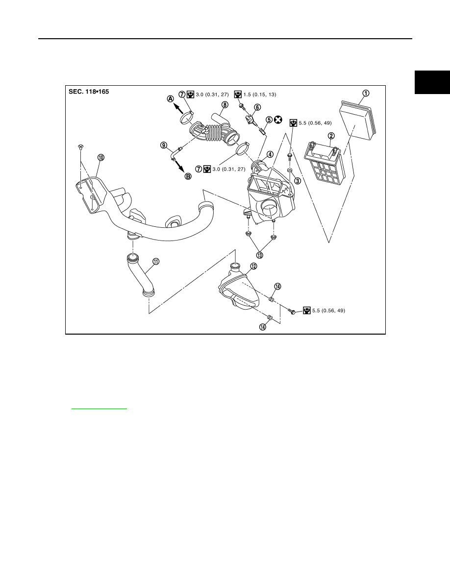
1.
Air cleaner filter
2.
Holder
3.
Grommet
4.
Air cleaner case
5.
O-ring
6.
Mass air flow sensor
7.
Clamp
8.
Air duct and resonator assembly
9.
PCV hose
10. Air duct (inlet)
11.
Air duct
12. Resonator
13. Grommet
14. Grommet
A.
To electric throttle control actuator
B.
To rocker cover
Refer to
for symbols in the figure.
JPBIA0277GB

Нет комментариевНе стесняйтесь поделиться с нами вашим ценным мнением.
Текст