Nissan Qashqai (2007-2010). Manual — part 565
MECHANICAL SYSTEM
TM-195
< FUNCTION DIAGNOSIS >
[CVT: RE0F10A]
C
E
F
G
H
I
J
K
L
M
A
B
TM
N
O
P
Component Description
INFOID:0000000000988609
JPDIA0129GB
TM-196
< FUNCTION DIAGNOSIS >
[CVT: RE0F10A]
MECHANICAL SYSTEM
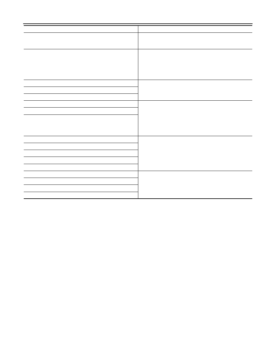
Item
Function
Torque converter
The torque converter is the device that increases the engine
torque as well as the conventional CVT and transmits it to the tran-
saxle.
Oil pump
The efficiency of pump discharge rate at low-rpm and the optimi-
zation at high-rpm have been increased through the oil pump drive
chain by adopting a vane-type oil pump controlled by the engine.
Discharged oil from oil pump is transmitted to the control valve. It
is used as the oil of primary and secondary pulley operation and
the oil of clutch operation and the lubricant for each part.
Planetary gear
Perform the transmission of drive power and the switching of for-
ward/backward movement.
Forward clutch
Reverse brake
Primary pulley
It is composed of a pair of pulleys (the groove width is changed
freely in the axial direction) and the steel belt (the steel star wheels
are placed continuously and the belt is guided with the multilayer
steel rings on both sides). The groove width changes according to
wrapping radius of steel belt and pulley from low status to over-
drive status continuously with non-step. It is controlled with the oil
pressures of primary pulley and secondary pulley.
Secondary pulley
Steel belt
Output gear
The drive power from the secondary pulley returns the decelera-
tion gears [primary deceleration (output gear/idler gear pair) and
secondary deceleration (reduction gear/final gear pair)]. It is trans-
mitted from differential to drive wheel.
Idler gear
Reduction gear
Final gear
Differential
Manual shaft
The parking rod rotates the parking pole and the parking pole en-
gages with the parking gear when the manual shaft is in P position.
As a result the parking gear and the output axis are fixed.
Parking rod
Parking pawl
Parking gear
HYDRAULIC CONTROL SYSTEM
TM-197
< FUNCTION DIAGNOSIS >
[CVT: RE0F10A]
C
E
F
G
H
I
J
K
L
M
A
B
TM
N
O
P
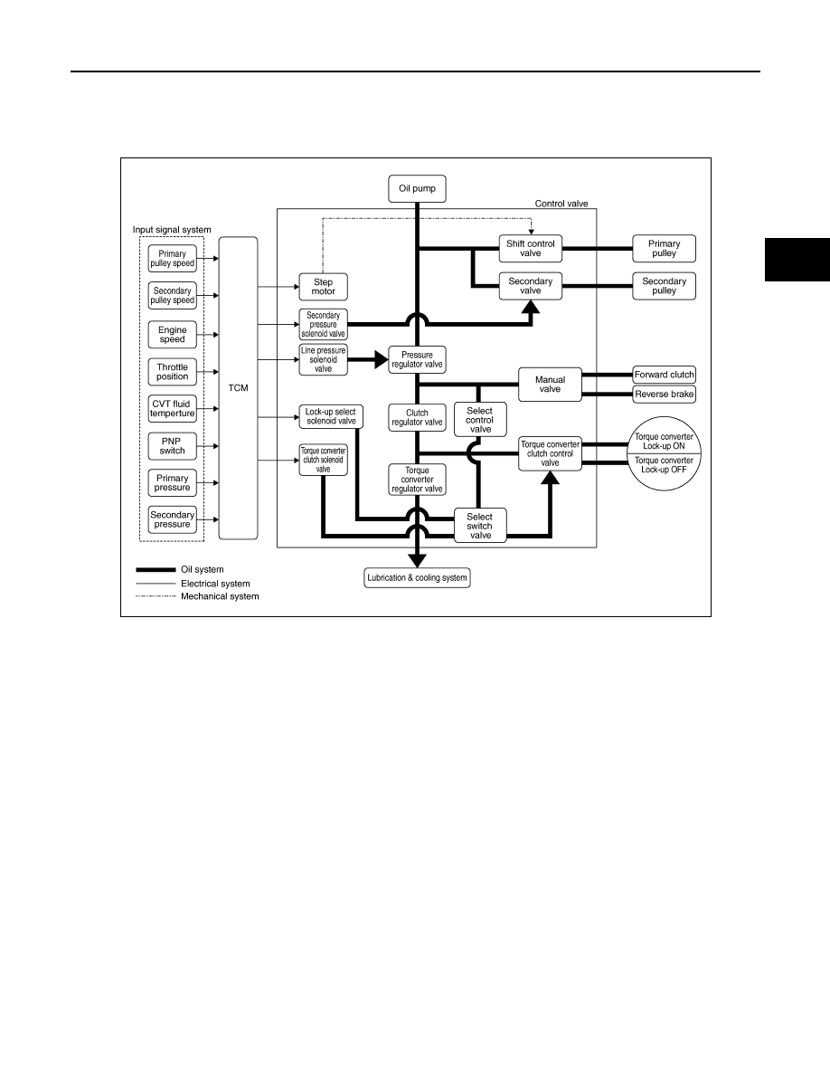
HYDRAULIC CONTROL SYSTEM
System Diagram
INFOID:0000000000988610
System Description
INFOID:0000000000988611
The hydraulic control mechanism consists of the oil pump directly driven by the engine, the hydraulic control
valve that controls line pressure and transmission, and the input signal line.
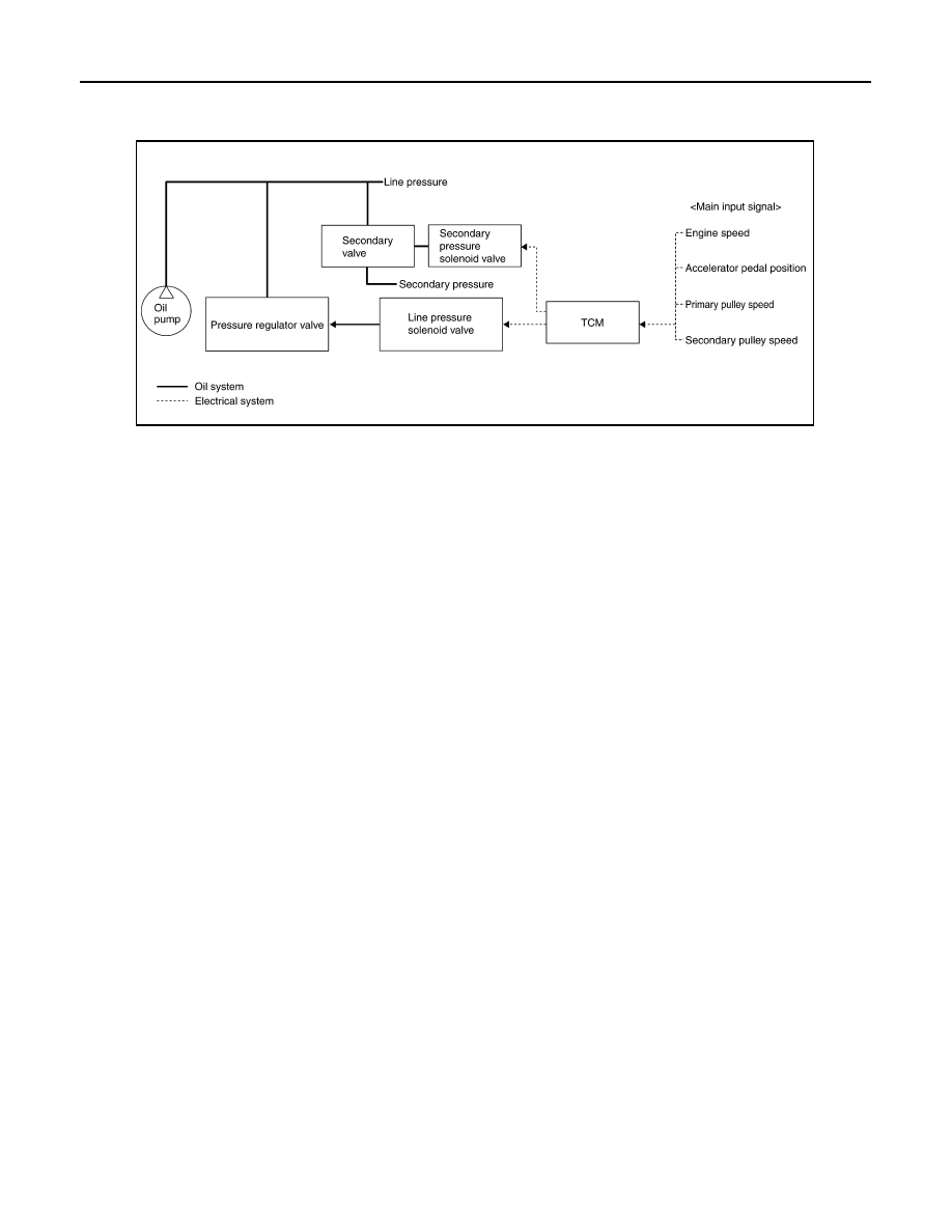
LINE PRESSURE AND SECONDARY PRESSURE CONTROL
• When an input torque signal equivalent to the engine drive force is sent from the ECM to the TCM, the TCM
controls the line pressure solenoid valve and secondary pressure solenoid valve.
JPDIA0307GB
TM-198
< FUNCTION DIAGNOSIS >
[CVT: RE0F10A]
HYDRAULIC CONTROL SYSTEM
• This line pressure solenoid controls the pressure regulator valve as the signal pressure and adjusts the pres-
sure of the operating oil discharged from the oil pump to the line pressure most appropriate to the driving
state. Secondary pressure is controlled by decreasing line pressure.
Normal Control
Optimize the line pressure and secondary pressure, depending on driving conditions, on the basis of the throt-
tle position, the engine speed, the primary pulley (input) revolution speed, the secondary pulley (output) revo-
lution speed, the brake signal, the PNP switch signal, the lock-up signal, the voltage, the target gear ratio, the
fluid temperature, and the fluid pressure.
Feedback Control
When controlling the normal fluid pressure or the selected fluid pressure, the secondary pressure can be set
more accurately by using the fluid pressure sensor to detect the secondary pressure and controlling the feed-
back.
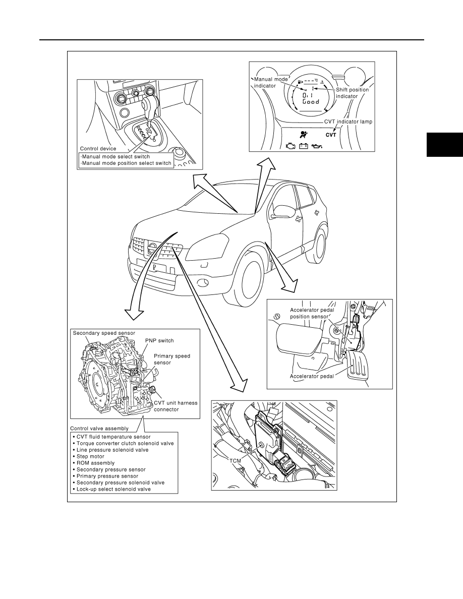
Component Parts Location
INFOID:0000000000988612
SCIA1846E
Нет комментариевНе стесняйтесь поделиться с нами вашим ценным мнением.
Текст