Nissan Qashqai (2007-2010). Manual — part 1118
INTELLIGENT KEY BATTERY
DLK-551
< ON-VEHICLE REPAIR >
[WITH I-KEY & SUPER LOCK]
C
D
E
F
G
H
I
J
L
M
A
B
DLK
N
O
P
INTELLIGENT KEY BATTERY
Exploded View
INFOID:0000000001109246
DLK-281, "Removal and Installation"
Removal and Installation
INFOID:0000000001109247
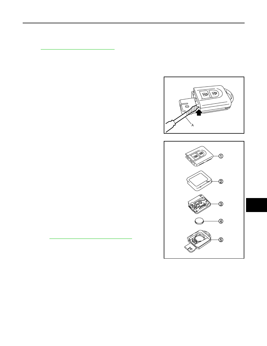
REMOVAL
1.
Remove Intelligent Key cover.
2.
Insert a flat-bladed screwdriver (A) wrapped with tape as shown
in the illustration and then separate lower and upper cases by
twisting screwdriver.
CAUTION:
• Do not touch the circuit board or battery terminal.
• The Intelligent Key is water-resistant. However, if it does
get wet, immediately wipe it dry.
3.
Remove the circuit board assembly from the upper case (1).
[Substrate assembly: circuit board (3) + rubber (2)]
4.
Gently press the rubber (2) and remove the circuit board (3).
CAUTION:
Do not touch the printed circuits directly.
5.
Remove the battery (4) from the lower case (5) and replace it.
CAUTION:
When replacing battery, keep dirt, grease, and other foreign
materials off the electrode contact area.
6.
After replacement, assemble the upper and lower cases by
engaging the hooks on their circumference while being careful
not to pinch the rubber, etc.
CAUTION:
After replacing the battery, check that all Intelligent Key
functions work normally.
Refer to
DLK-134, "Component Function Check"
INSTALLATION
Install in the reverse order of removal.
MIIB0661E
Battery replacement
: Coin-type lithium battery
(CR2032)
MIIB0662E
DLK-552
< ON-VEHICLE REPAIR >
[WITH I-KEY & SUPER LOCK]
INTELLIGENT KEY UNIT
INTELLIGENT KEY UNIT
Exploded View
INFOID:0000000001116437
DLK-551, "Removal and Installation"
Removal and Installation
INFOID:0000000001116438
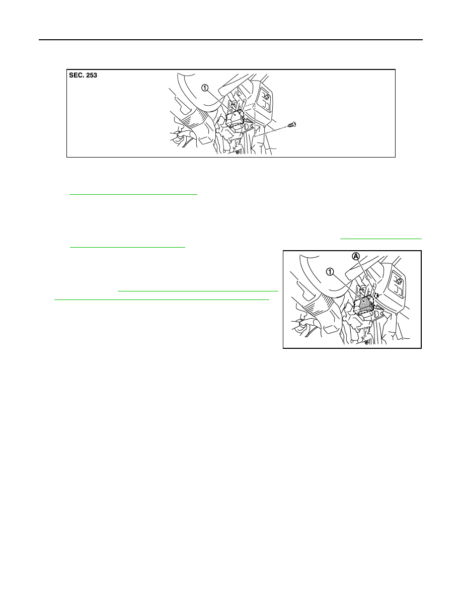
REMOVAL
1.
Remove lower instrument panel (driver side) and mirror switch finisher. Refer to
and
IP-12, "Removal and Installation"
2.
Remove the Intelligent Key unit mounting screw (A), and then
remove Intelligent Key unit (1).
NOTE:
Perform the system initialization when replacing Intelligent Key
unit. Refer to
DLK-23, "ADDITIONAL SERVICE WHEN
REPLACING CONTROL UNIT : Special Repair Requirement"
INSTALLATION
Install in the reverse order of removal.
JMKIA0538ZZ
1.
Intelligent Key unit
M40
JMKIA0539ZZ
DIAGNOSIS AND REPAIR WORKFLOW
DLK-553
< BASIC INSPECTION >
[WITHOUT I-KEY & SUPER LOCK]
C
D
E
F
G
H
I
J
L
M
A
B
DLK
N
O
P
BASIC INSPECTION
DIAGNOSIS AND REPAIR WORKFLOW
Work Flow
INFOID:0000000001102242
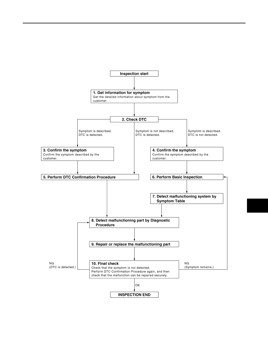
OVERALL SEQUENCE
DETAILED FLOW
JMKIA0101GB

DLK-554
< BASIC INSPECTION >
[WITHOUT I-KEY & SUPER LOCK]
DIAGNOSIS AND REPAIR WORKFLOW
1.
GET INFORMATION FOR SYMPTOM
Get the detailed information from the customer about the symptom (the condition and the environment when
the incident/malfunction occurred).
>> GO TO 2.
2.
CHECK DTC
1.
Check DTC for BCM.
2.
Perform the following procedure if DTC is displayed.
-
Erase DTC.
-
Study the relationship between the cause detected by DTC and the symptom described by the customer.
3.
Check related service bulletins for information.
Is any symptom described and any DTC detected?
Symptom is described, DTC is displayed>>GO TO 3.
Symptom is described, DTC is not displayed>>GO TO 4.
Symptom is not described, DTC is displayed>>GO TO 5.
3.
CONFIRM THE SYMPTOM
Confirm the symptom described by the customer.
Connect CONSULT-III to the vehicle in “DATA MONITOR” mode and check real time diagnosis results.
Verify relation between the symptom and the condition when the symptom is detected.
>> GO TO 5.
4.
CONFIRM THE SYMPTOM
Confirm the symptom described by the customer.
Connect CONSULT-III to the vehicle in “DATA MONITOR ” mode and check real time diagnosis results.
Verify relation between the symptom and the condition when the symptom is detected.
>> GO TO 6.
5.
PERFORM DTC CONFIRMATION PROCEDURE
Perform DTC Confirmation Procedure for the displayed DTC, and then check that DTC is detected again.
If two or more DTCs are detected, refer to
DLK-643, "DTC Inspection Priority Chart"
and determine trouble
diagnosis order.
Is DTC detected?
YES
>> GO TO 8.
NO
>> Refer to
GI-39, "Intermittent Incident"
.
6.
PERFORM BASIC INSPECTION
Perform Basic Inspection, refer to
Inspection End>>GO TO 7.
7.
DETECT MALFUNCTIONING SYSTEM BY SYMPTOM TABLE
Detect malfunctioning system according to Symptom Table based on the confirmed symptom in step 4.
>> GO TO 8.
8.
DETECT MALFUNCTIONING PART BY DIAGNOSTIC PROCEDURE
Inspect according to Diagnostic Procedure of the system.
NOTE:
The Diagnostic Procedure described based on open circuit inspection. A short circuit inspection is also
required for the circuit check in the Diagnostic Procedure.
>> GO TO 9.
Нет комментариевНе стесняйтесь поделиться с нами вашим ценным мнением.
Текст