Nissan Qashqai (2007-2010). Manual — part 720

BRC-78
< BASIC INSPECTION >
[ESP/TCS/ABS]
INSPECTION AND ADJUSTMENT
INSPECTION AND ADJUSTMENT
ADDITIONAL SERVICE WHEN REPLACING CONTROL UNIT
ADDITIONAL SERVICE WHEN REPLACING CONTROL UNIT : Description
INFOID:0000000000924791
After replacing the ABS actuator and electric unit (control unit), perform the neutral position adjustment for the
steering angle sensor.
ADDITIONAL SERVICE WHEN REPLACING CONTROL UNIT : Special Repair Re-
quirement
INFOID:0000000000924792
1.
PERFORM THE NEUTRAL POSITION ADJUSTMENT FOR THE STEERING ANGLE SENSOR
Perform the neutral position adjustment for the steering angle sensor.
>> Refer to
BRC-78, "ADJUSTMENT OF STEERING ANGLE SENSOR NEUTRAL POSITION : Spe-
.
ADJUSTMENT OF STEERING ANGLE SENSOR NEUTRAL POSITION
ADJUSTMENT OF STEERING ANGLE SENSOR NEUTRAL POSITION : Description
INFOID:0000000000924793
In case of doing work that applies to the list below, make sure to adjust neutral position of steering angle sen-
sor before running vehicle.
×
: Required –: Not required
ADJUSTMENT OF STEERING ANGLE SENSOR NEUTRAL POSITION : Special Re-
pair Requirement
INFOID:0000000000924794
ADJUSTMENT OF STEERING ANGLE SENSOR NEUTRAL POSITION
CAUTION:
To adjust neutral position of steering angle sensor, make sure to use CONSULT-III.
(Adjustment cannot be done without CONSULT-III).
1.
ALIGN THE VEHICLE STATUS
Stop vehicle with front wheels in straight-ahead position.
>> GO TO 2.
2.
PERFORM THE NEUTRAL POSITION ADJUSTMENT FOR THE STEERING ANGLE SENSOR
1.
On the CONSULT-III screen, touch "WORK SUPPORT" and "ST ANG SEN ADJUSTMENT" in order.
2.
Touch “START”.
Situation
Adjustment of steering angle sensor neutral position
Removing/Installing ABS actuator and electric unit (control unit)
—
Replacing ABS actuator and electric unit (control unit)
×
Removing/Installing steering angle sensor
×
Replacing steering angle sensor
×
Removing/Installing steering components
×
Replacing steering components
×
Removing/Installing suspension components
×
Replacing suspension components
×
Change tires to new ones
—
Tire rotation
—
Adjusting wheel alignment
×

INSPECTION AND ADJUSTMENT
BRC-79
< BASIC INSPECTION >
[ESP/TCS/ABS]
C
D
E
G
H
I
J
K
L
M
A
B
BRC
N
O
P
CAUTION:
Do not touch steering wheel while adjusting steering angle sensor.
3.
After approximately 10 seconds, touch “END”.
NOTE:
After approximately 60 seconds, it ends automatically.
4.
Turn ignition switch OFF, then turn it ON again.
CAUTION:
Be sure to perform above operation.
>> GO TO 3.
3.
CHECK DATA MONITOR
1.
Run vehicle with front wheels in straight-ahead position, then stop.
2.
Select “DATA MONITOR”. Then make sure “STR ANGLE SIG” is within 0
±
2.5
°
.
Is the steering angle within the specified range?
YES
>> GO TO 4.
NO
>> Perform the neutral position adjustment for the steering angle sensor again, GO TO 1.
4.
ERASE THE SELF-DIAGNOSIS MEMORY
Erase the self-diagnosis memories of the ABS actuator and electric unit (control unit) and ECM.
• ABS actuator and electric unit (control unit): Refer to
BRC-96, "CONSULT-III Function (ABS)"
.
• ECM
- HR16DE (With EURO-OBD):
EC-100, "CONSULT-III Function"
- HR16DE (Without EURO-OBD):
EC-430, "CONSULT-III Function"
- MR20DE (With EURO-OBD):
EC-719, "CONSULT-III Function"
- MR20DE (Without EURO-OBD):
EC-1054, "CONSULT-III Function"
.
EC-1315, "Diagnosis Description"
Are the memories erased?
YES
>> INSPECTION END
NO
>> Check the items indicated by the self-diagnosis.
BRC-80
< FUNCTION DIAGNOSIS >
[ESP/TCS/ABS]
ESP
FUNCTION DIAGNOSIS
ESP
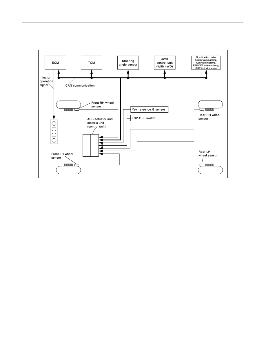
System Diagram
INFOID:0000000000924795
System Description
INFOID:0000000000924796
• Electronic Stability Program system detects driver
′
s steering operation amount and brake pedal travel from
steering angle sensor and pressure sensor. Using information from yaw rate sensor, G sensor and wheel
sensor, ESP judges driving condition (conditions of under steer and over steer) to improve vehicle driving
stability by controlling brake application to 4 wheels and engine output.
• During ESP operation, it informs driver of system operation by flashing SLIP indicator lamp.
• Electrical system diagnosis by CONSULT-III is available.
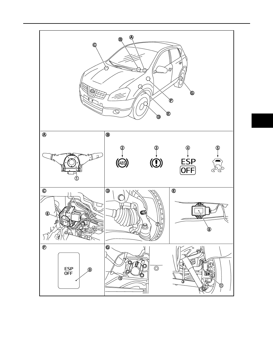
Component Parts Location
INFOID:0000000000924797
JSFIA0070GB
ESP
BRC-81
< FUNCTION DIAGNOSIS >
[ESP/TCS/ABS]
C
D
E
G
H
I
J
K
L
M
A
B
BRC
N
O
P
LHD models
JSFIA0032ZZ
1.
Steering angle sensor
2.
ABS warning lamp
3.
Brake warning lamp
4.
ESP OFF indicator lamp
5.
SLIP indicator lamp
6.
ABS actuator and electric unit (con-
trol unit)
7.
Front wheel sensor
8.
Yaw rate/side G sensor
9.
ESP OFF switch
10. Rear wheel sensor (2WD models)
11.
Rear wheel sensor (4WD models)
A.
Back of spiral cable assembly
B.
Combination meter
C.
Right side in engine room
Нет комментариевНе стесняйтесь поделиться с нами вашим ценным мнением.
Текст