Nissan Qashqai (2007-2010). Manual — part 472
P2263 TC SYSTEM
EC-1407
< COMPONENT DIAGNOSIS >
[K9K]
C
D
E
F
G
H
I
J
K
L
M
A
EC
N
P
O
Check turbocharger.
Is the inspection result normal?
Yes
>> Repair or replace.
No
>> GO TO 6.
6.
CHECK TURBOCHARGER BOOST CONTROL SOLENOID VALVE POWER SUPPLY CIRCUIT
1.
Disconnect turbocharger boost control solenoid valve harness connector.
2.
Turn ignition switch ON.
3.
Check the voltage between turbocharger boost control solenoid valve harness connector and ground.
Is the inspection result normal?
YES
>> GO TO 7.
NO
>> Repair open circuit or short to ground or short to power in harness or connectors.
7.
CHECK TURBOCHARGER BOOST CONTROL SOLENOID VALVE OUTPUT SIGNAL CIRCUIT FOR
OPEN AND SHORT
1.
Turn ignition switch OFF.
2.
Disconnect ECM harness connector.
3.
Check the continuity between turbocharger boost control solenoid valve harness connector and ECM har-
ness connector.
4.
Also check harness for short to ground and short to power.
Is the inspection result normal?
YES
>> GO TO 8.
NO
>> Repair open circuit or short to ground or short to power in harness or connectors.
8.
CHECK TURBOCHARGER BOOST CONTROL SOLENOID VALVE
EC-1328, "Component Inspection"
.
Is the inspection result normal?
YES
>> GO TO 9.
NO
>> Replace turbocharger boost control solenoid valve.
9.
CHECK TURBOCHARGER BOOST SENSOR
EC-1330, "Component Inspection"
.
Is the inspection result normal?
YES
>> GO TO 10.
NO
>> Replace turbocharger boost sensor.
10.
CHECK THROTTLE CONTROL MOTOR
EC-1405, "Component Inspection"
.
Is the inspection result normal?
YES
>> GO TO 11.
NO
>> Replace turbocharger boost sensor.
11.
CHECK INTERMITTENT INCIDENT
GI-39, "Intermittent Incident"
.
>> INSPECTION END
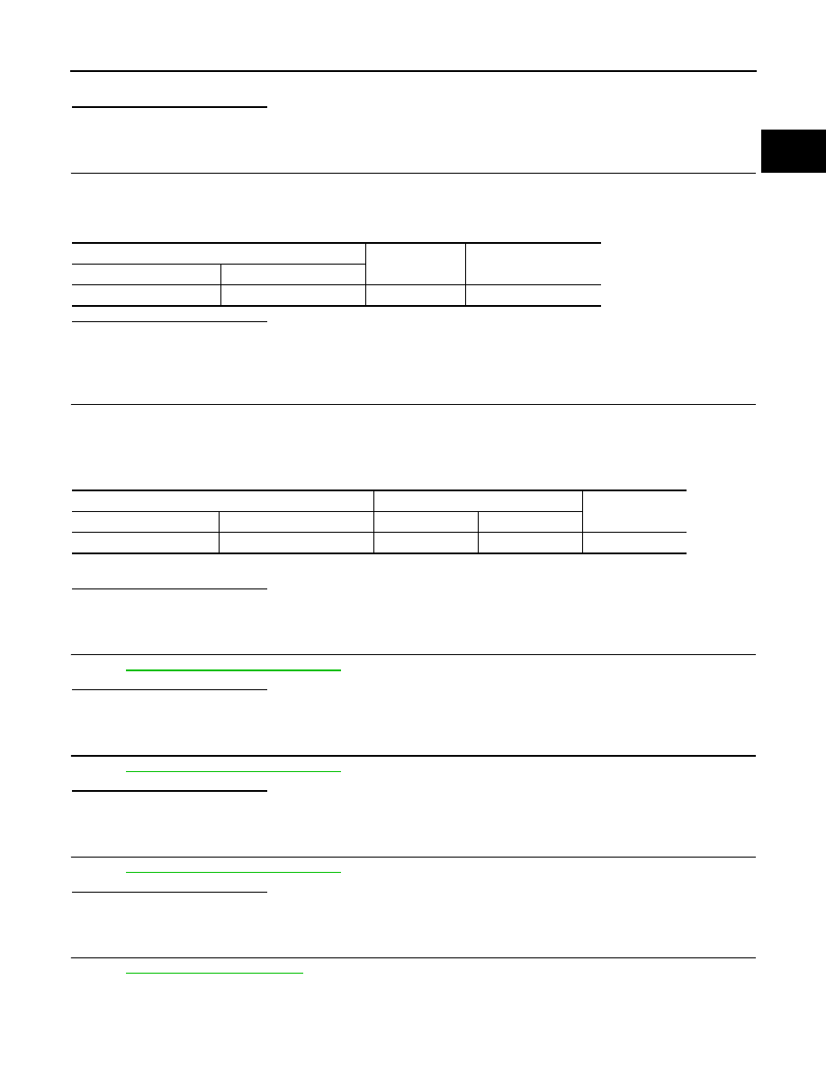
Turbocharger boost control solenoid valve
Ground
Voltage
Connector
Terminal
E55
2
Ground
Battery voltage
Turbocharger boost control solenoid valve
ECM
Continuity
Connector
Terminal
Connector
Terminal
E55
1
F68
52
Existed

EC-1408
< COMPONENT DIAGNOSIS >
[K9K]
P2299 ACCELERATOR/BRAKE PEDAL POSITION INCONSISTENCY
P2299 ACCELERATOR/BRAKE PEDAL POSITION INCONSISTENCY
DTC Logic
INFOID:0000000001115113
DTC DETECTION LOGIC
NOTE:
• Special note:
The brake and accelerator pedals were detected as depressed simultaneously for 30 seconds.
• If the DTC is present:
- Malfunction indicator (Red) lights up.
Diagnosis Procedure
INFOID:0000000000970929
1.
CHECK GROUND CONNECTIONS
1.
Turn ignition switch OFF.
2.
Check ground connection E17. Refer to Ground inspection in
Is the inspection result normal?
YES
>> GO TO 2.
NO
>> Repair or replace ground connection.
2.
CHECK BRAKE SWITCH CIRCUIT
1.
Turn ignition switch ON.
2.
Check the voltage between ECM harness connector and ground.
Is the inspection result normal?
YES
>> GO TO 3.
NO
>> GO TO 7.
3.
CHECK ACCELERATOR PEDAL POSITION SENSOR POWER SUPPLY CIRCUIT
1.
Turn ignition switch OFF.
2.
Disconnect accelerator pedal position sensor harness connector.
3.
Turn ignition switch ON.
4.
Check the voltage between accelerator pedal position sensor connector and ground.
Is the inspection result normal?
YES
>> GO TO 4.
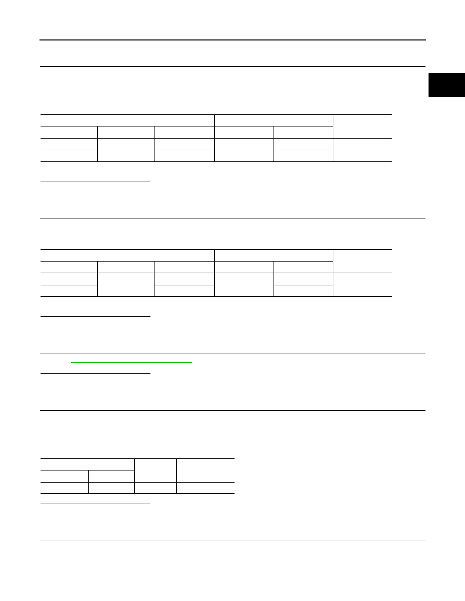
DTC No.
Trouble diagnosis name
Possible cause
P2299
ACCELERATOR PEDAL/BRAKE PEDAL INCONSISTENCY
• 1.DEF: Inconsistency
• Harness or connectors
(APP sensor 1 and 2 circuit is open or
shorted.)
(Stop lamp switch circuit is open or short-
ed.)
• Accelerator pedal position sensor
(APP sensor 1 and 2.)
• Stop lamp switch
• Accelerator pedal
ECM
Ground
Condition
Voltage
Connector
Terminal
E60
115
(ASCD brake switch)
Ground
Brake pedal
Fully released
0V
Slightly depressed
Battery voltage
Accelerator pedal position sensor
Ground
Voltage
Sensor
Connector
Terminal
1
E110
4
Ground
Approx. 5V
2
5
P2299 ACCELERATOR/BRAKE PEDAL POSITION INCONSISTENCY
EC-1409
< COMPONENT DIAGNOSIS >
[K9K]
C
D
E
F
G
H
I
J
K
L
M
A
EC
N
P
O
NO
>> Repair open circuit or short to ground or short to power in harness or connectors.
4.
CHECK ACCELERATOR PEDAL POSITION SENSOR GROUND CIRCUIT FOR OPEN AND SHORT
1.
Turn ignition switch OFF.
2.
Disconnect ECM harness connector.
3.
Check the continuity between accelerator pedal position sensor harness connector and ECM harness
connector.
4.
Also check harness for short to ground and short to power.
Is the inspection result normal?
YES
>> GO TO 5.
NO
>> Repair open circuit or short to ground or short to power in harness or connectors.
5.
CHECK ACCELERATOR PEDAL POSITION SENSOR INPUT SIGNAL CIRCUIT FOR OPEN AND SHORT
1.
Check the continuity between accelerator pedal position sensor harness connector and ECM harness
connector.
2.
Also check harness for short to ground and short to power.
Is the inspection result normal?
YES
>> GO TO 6.
NO
>> Repair open circuit or short to ground or short to power in harness or connectors.
6.
CHECK ACCELERATOR PEDAL POSITION SENSOR
EC-1359, "Component Inspection"
.
Is the inspection result normal?
YES
>> GO TO 11.
NO
>> Replace accelerator pedal position sensor.
7.
CHECK BRAKE SWITCH POWER SUPPLY CIRCUIT
1.
Turn ignition switch OFF.
2.
Disconnect stop lamp switch harness connector.
3.
Turn ignition switch ON.
4.
Check the voltage between stop lamp switch harness connector and ground.
Is the inspection result normal?
YES
>> GO TO 9.
NO
>> GO TO 8.
8.
DETECT MALFUNCTIONING PART
Check the following.
• Harness connector E105, M77
• 10A fuse (No. 11)
• Harness for open or short between fuse and stop lamp switch
Accelerator pedal position sensor
ECM
Continuity
Sensor
Connector
Terminal
Connector
Terminal
1
E110
2
E60
127
Existed
2
1
120
Accelerator pedal position sensor
ECM
Continuity
Sensor
Connector
Terminal
Connector
Terminal
1
E110
3
E60
126
Existed
2
6
119
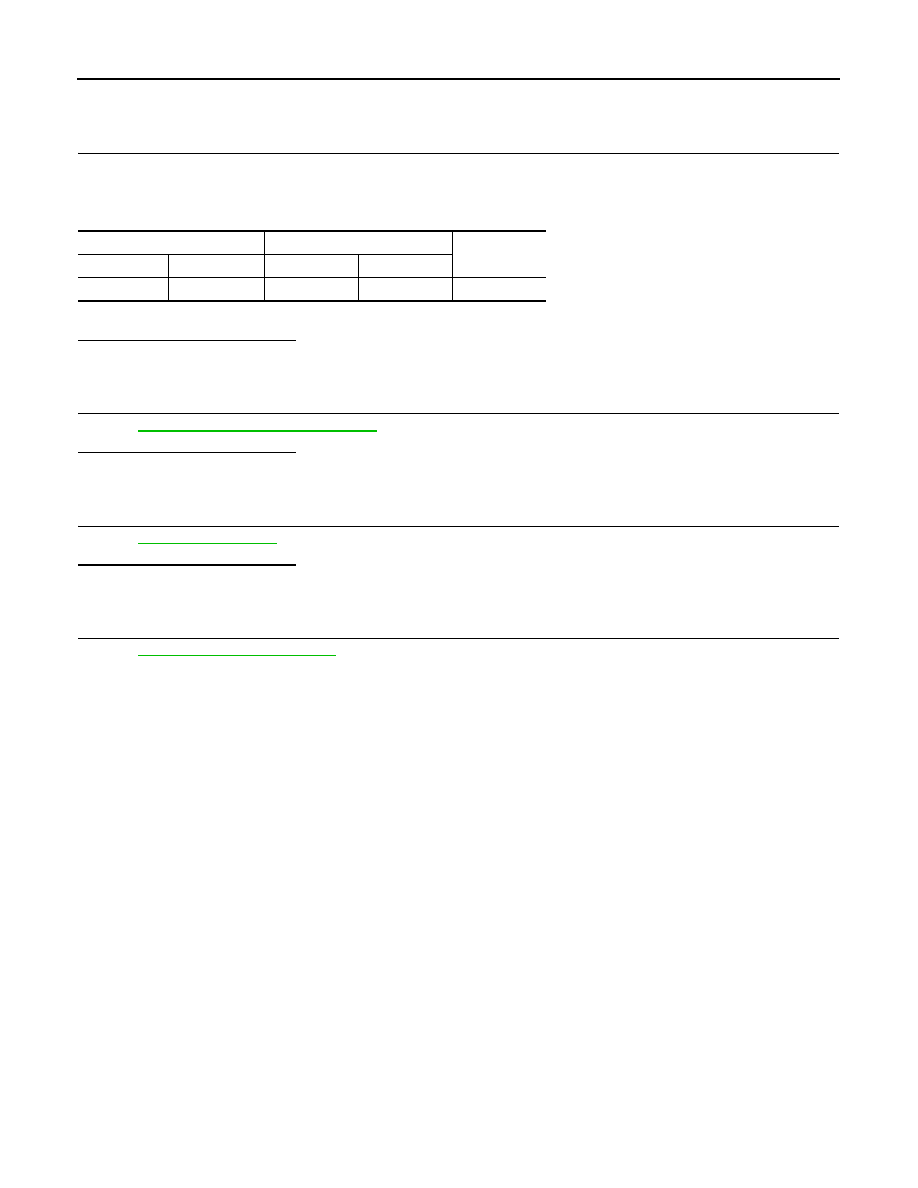
Stop lamp switch
Ground
Voltage
Connector
Terminal
E115
1
Ground
Battery voltage
EC-1410
< COMPONENT DIAGNOSIS >
[K9K]
P2299 ACCELERATOR/BRAKE PEDAL POSITION INCONSISTENCY
>> Repair open circuit or short to ground or short to power in harness or connectors.
9.
CHECK BRAKE SWITCH INPUT SIGNAL CIRCUIT
1.
Turn ignition switch OFF.
2.
Disconnect ECM harness connector.
3.
Check the continuity between stop lamp switch harness connector and ECM harness connector.
4.
Also check harness for short to ground and short to power.
Is the inspection result normal?
YES
>> GO TO 10.
NO
>> Repair open circuit or short to ground or short to power in harness or connectors.
10.
CHECK STOP LAMP SWITCH
EC-1359, "Component Inspection"
.
Is the inspection result normal?
YES
>> GO TO 11.
NO
>> Replace stop lamp switch.
11.
CHECK ACCELERATOR PEDAL
.
Is the inspection result normal?
YES
>> GO TO 12.
NO
>> Replace accelerator pedal position sensor.
12.
CHECK INTERMITTENT INCIDENT
GI-39, "Intermittent Incident"
>> INSPECTION END
Stop lamp switch
ECM
Continuity
Connector
Terminal
Connector
Terminal
E115
2
E60
115
Existed
Нет комментариевНе стесняйтесь поделиться с нами вашим ценным мнением.
Текст