Nissan Qashqai (2007-2010). Manual — part 1273
DIAGNOSIS SYSTEM (BCM)
PWC-9
< FUNCTION DIAGNOSIS >
C
D
E
F
G
H
I
J
L
M
A
B
PWC
N
O
P
DIAGNOSIS SYSTEM (BCM)
COMMON ITEM
COMMON ITEM : CONSULT-III Function (BCM - COMMON ITEM)
INFOID:0000000001116527
APPLICATION ITEM
CONSULT-III performs the following functions via CAN communication with BCM.
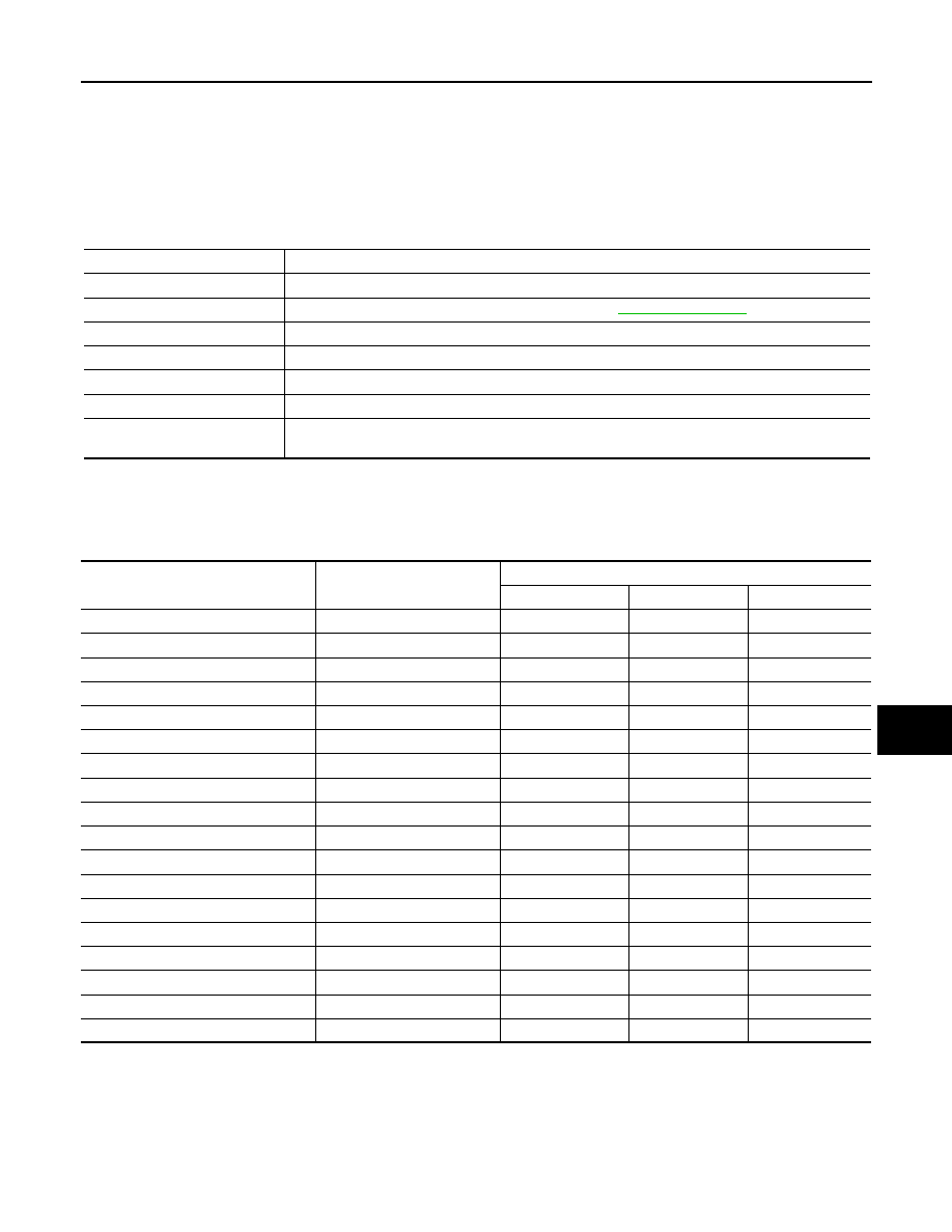
SYSTEM APPLICATION
BCM can perform the following functions for each system.
NOTE:
It can perform the diagnosis modes except the following for all sub system selection items.
Diagnosis mode
Function Description
WORK SUPPORT
Changes the setting for each system function.
SELF-DIAG RESULTS
Displays the diagnosis results judged by BCM. Refer to
CAN DIAG SUPPORT MNTR
Monitors the reception status of CAN communication viewed from BCM.
DATA MONITOR
The BCM input/output signals are displayed.
ACTIVE TEST
The signals used to activate each device are forcibly supplied from BCM.
ECU IDENTIFICATION
The BCM part number is displayed.
CONFIGURATION
• Enables to read and save the vehicle specification.
• Enables to write the vehicle specification when replacing BCM.
System
Sub system selection item
Diagnosis mode
WORK SUPPORT
DATA MONITOR
ACTIVE TEST
—
BCM
×
Door lock
DOOR LOCK
×
×
×
Rear window defogger
REAR DEFOGGER
×
×
Warning chime
BUZZER
×
×
Interior room lamp timer
INT LAMP
×
×
×
Remote keyless entry system
MULTI REMOTE ENT
×
×
×
Exterior lamp
HEAD LAMP
×
×
×
Wiper and washer
WIPER
×
×
×
Turn signal and hazard warning lamps
FLASHER
×
×
Air conditioner
AIR CONDITONER
×
Intelligent Key system
INTELLIGENT KEY
×
Combination switch
COMB SW
×
Immobilizer
IMMU
×
×
Interior room lamp battery saver
BATTERY SAVER
×
×
×
Trunk open
TRUNK
×
Vehicle security system
THEFT ALM
×
×
×
Signal buffer system
SIGNAL BUFFER
×
×
PTC heater system
PTC HEATER
×
×
PWC-10
< COMPONENT DIAGNOSIS >
POWER SUPPLY AND GROUND CIRCUIT
COMPONENT DIAGNOSIS
POWER SUPPLY AND GROUND CIRCUIT
POWER WINDOW MAIN SWITCH
POWER WINDOW MAIN SWITCH : Description
INFOID:0000000000990487
• BCM supplies power.
• It operates each power window motor via corresponding power window switch and makes window move up/
down when power window main switch is operated.
POWER WINDOW MAIN SWITCH : Component Function Check
INFOID:0000000000990488
Power Window Main Switch
1.
CHECK POWER WINDOW MAIN SWITCH FUNCTION
Does power window motor operate with power window main switch operation?
Is the inspection result normal?
YES
>> Power window main switch power supply and ground circuit are OK.
NO
>> Refer to
PWC-10, "POWER WINDOW MAIN SWITCH : Diagnosis Procedure"
POWER WINDOW MAIN SWITCH : Diagnosis Procedure
INFOID:0000000000990489
Power Window Main Switch Power Supply Circuit Check
1.
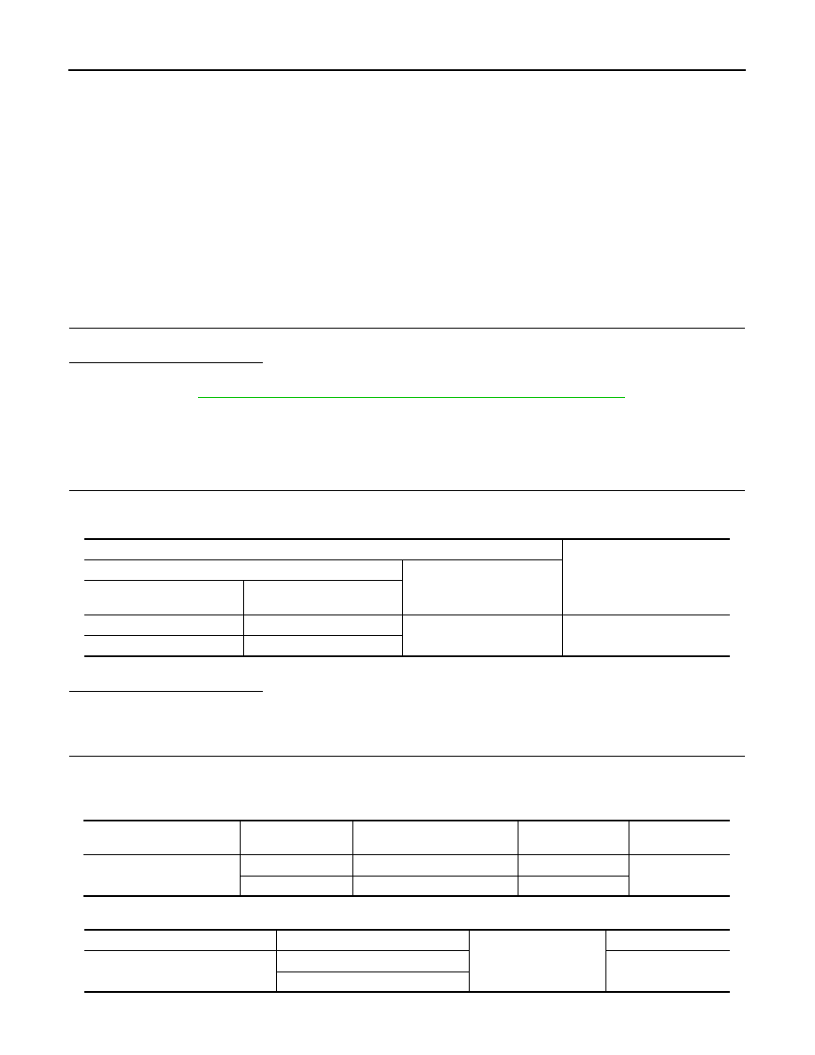
CHECK POWER SUPPLY CIRCUIT
1.
Turn ignition switch ON.
2.
Check voltage between power window main switch connector and ground.
():RHD models
Is the inspection result normal?
YES
>> GO TO 3.
NO
>> GO TO 2.
2.
CHECK HARNESS CONTINUITY
1.
Turn ignition switch OFF.
2.
Disconnect BCM connector and power window main switch connector.
3.
Check continuity between BCM connector and power window main switch connector.
4.
Check continuity between BCM connector and ground.
():RHD models
Terminal
Voltage (V)
(Approx.)
(+)
(–)
Power window main switch
connector
Terminal
D5 (D25)
10
Ground
Battery voltage
D6 (D26)
19
BCM connector
Terminal
Power window main switch
connector
Terminal
Continuity
M67
53
D5 (D25)
10
Existed
58
D6 (D26)
19
BCM connector
Terminal
Ground
Continuity
M67
53
Not existed
58
POWER SUPPLY AND GROUND CIRCUIT
PWC-11
< COMPONENT DIAGNOSIS >
C
D
E
F
G
H
I
J
L
M
A
B
PWC
N
O
P
Is the inspection result normal?
YES
>> GO TO 4.
NO
>> Repair or replace harness.
3.
CHECK GROUND CIRCUIT
1.
Turn ignition switch OFF.
2.
Disconnect power window main switch connector.
3.
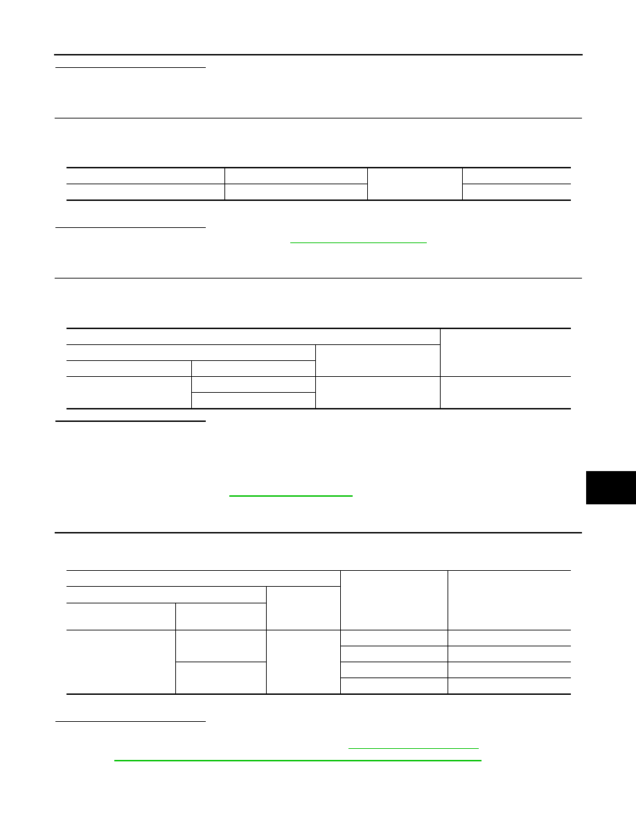
Check continuity between power window main switch connector and ground.
():RHD models
Is the inspection result normal?
YES
>> Check intermittent incident. Refer to
GI-39, "Intermittent Incident"
.
NO
>> Repair or replace harness.
4.
CHECK BCM OUTPUT SIGNAL
1.
Connect BCM connector.
2.
Turn ignition switch ON.
3.
Check voltage between BCM connector and ground.
Is the inspection result normal?
YES
>> Check power window main switch output signal (front power window switch driver side) GO TO 5.
YES
>> Check power window main switch output signal (front power window switch passenger side) GO
TO 6.
YES
>> Check power window main switch output signal (rear power window switch LH) GO TO 7.
YES
>> Check power window main switch output signal (rear power window switch RH) GO TO 8.
NO
>> Replace BCM. Refer to
.
5.
CHECK POWER WINDOW MAIN SWITCH OUTPUT SIGNAL (FRONT POWER WINDOW SWITCH DRIV-
ER SIDE)
1.
Turn ignition switch ON.
2.
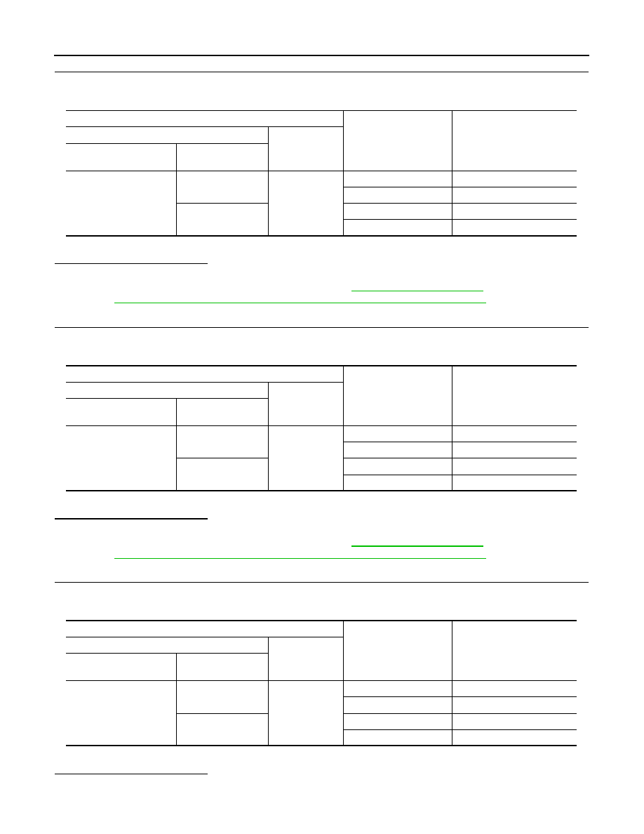
Check voltage between power window main switch and ground.
():RHD models
Is the inspection result normal?
YES
>> Power window main switch is OK.
NO
>> Replace power window main switch. Refer to
. After that, Refer to
PWC-15, "POWER WINDOW MAIN SWITCH : Special Repair Requirement"
.
6.
CHECK POWER WINDOW MAIN SWITCH OUTPUT SIGNAL (FRONT POWER WINDOW SWITCH PAS-
Power window main switch connector
Terminal
Ground
Continuity
D6 (D26)
17
Existed
Terminals
Voltage (V)
(Approx.)
(+)
(–)
BCM connector
Terminal
M67
53
Ground
Battery voltage
58
Terminal
Window
condition
Voltage (V)
(Approx.)
(+)
(–)
Power window main
switch connector
Terminal
D5 (D25)
16
Ground
UP
Battery voltage
DOWN
0
12
UP
0
DOWN
Battery voltage
PWC-12
< COMPONENT DIAGNOSIS >
POWER SUPPLY AND GROUND CIRCUIT
SENGER SIDE)
1.
Turn ignition switch ON.
2.
Check voltage between power window main switch and ground.
():RHD models
Is the inspection result normal?
YES
>> GO TO 9.
NO
>> Replace power window main switch. Refer to
. After that, Refer to
PWC-15, "POWER WINDOW MAIN SWITCH : Special Repair Requirement"
.
7.
CHECK POWER WINDOW MAIN SWITCH OUTPUT SIGNAL (REAR POWER WINDOW SWITCH LH)
1.
Turn ignition switch ON.
2.
Check voltage between power window main switch and ground.
():RHD models
Is the inspection result normal?
YES
>> GO TO 10.
NO
>> Replace power window main switch. Refer to
. After that, Refer to
PWC-15, "POWER WINDOW MAIN SWITCH : Special Repair Requirement"
.
8.
CHECK POWER WINDOW MAIN SWITCH OUTPUT SIGNAL (REAR POWER WINDOW SWITCH RH)
1.
Turn ignition switch ON.
2.
Check voltage between power window main switch and ground.
():RHD models
Is the inspection result normal?
YES
>> GO TO 11.
Terminal
Window
condition
Voltage (V)
(Approx.)
(+)
(–)
Power window main
switch connector
Terminal
D5 (D25)
8
Ground
UP
Battery voltage
DOWN
0
11
UP
0
DOWN
Battery voltage
Terminal
Window
condition
Voltage (V)
(Approx.)
(+)
(–)
Power window main
switch connector
Terminal
D5 (D25)
1
Ground
UP
Battery voltage
DOWN
0
3
UP
0
DOWN
Battery voltage
Terminal
Window
condition
Voltage (V)
(Approx.)
(+)
(–)
Power window main
switch connector
Terminal
D5 (D25)
7
Ground
UP
Battery voltage
DOWN
0
5
UP
0
DOWN
Battery voltage
Нет комментариевНе стесняйтесь поделиться с нами вашим ценным мнением.
Текст