Nissan Qashqai (2007-2010). Manual — part 371
MULTIPORT FUEL INJECTION SYSTEM
EC-1003
< FUNCTION DIAGNOSIS >
[MR20DE (WITHOUT EURO-OBD)]
C
D
E
F
G
H
I
J
K
L
M
A
EC
N
P
O
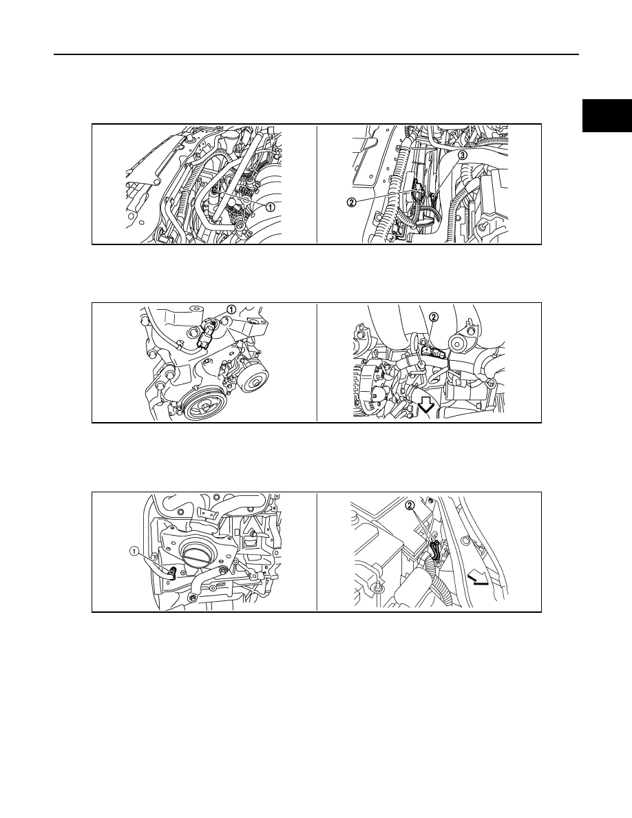
1.
PCV valve
2.
Ignition coil (with power transistor)
and spark plug
3.
Fuel injection
1.
Refrigerant pressure sensor
2.
Resister
3.
Cooling fan motor
1.
Intake valve timing control solenoid
valve
2.
Knock sensor
1.
Crankshaft position sensor (POS)
2.
Ground
JMBIA0345ZZ
JMBIA0445ZZ
JMBIA0446ZZ
EC-1004
< FUNCTION DIAGNOSIS >
[MR20DE (WITHOUT EURO-OBD)]
MULTIPORT FUEL INJECTION SYSTEM
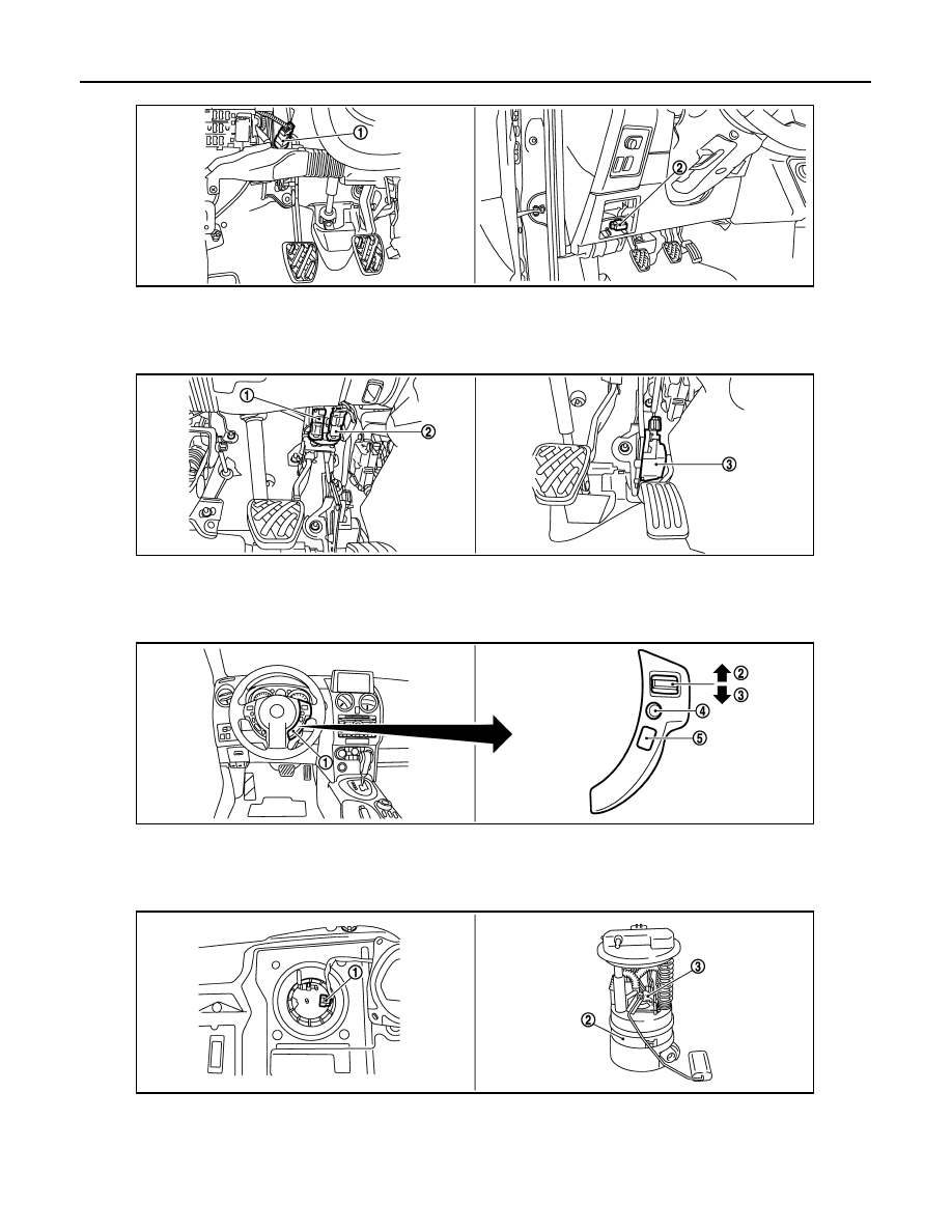
1.
ASCD clutch switch
2.
Data link connector
1.
Stop lamp switch
2.
ASCD brake switch
3.
Accelerator pedal position sensor
1.
ASDC steering switch
2.
CANSEL switch
3.
RESUME/ACCCELERATE switch
4.
SET/COAST switch
5.
MAIN SWITCH
6.
1.
Fuel level sensor unit and fuel pump
harness connector
2.
Fuel level sensor unit and fuel pump 3.
Fuel pressure regulator
JMBIA0347ZZ
JMBIA0348ZZ
JMBIA0349ZZ
JMBIA0346ZZ
MULTIPORT FUEL INJECTION SYSTEM
EC-1005
< FUNCTION DIAGNOSIS >
[MR20DE (WITHOUT EURO-OBD)]
C
D
E
F
G
H
I
J
K
L
M
A
EC
N
P
O
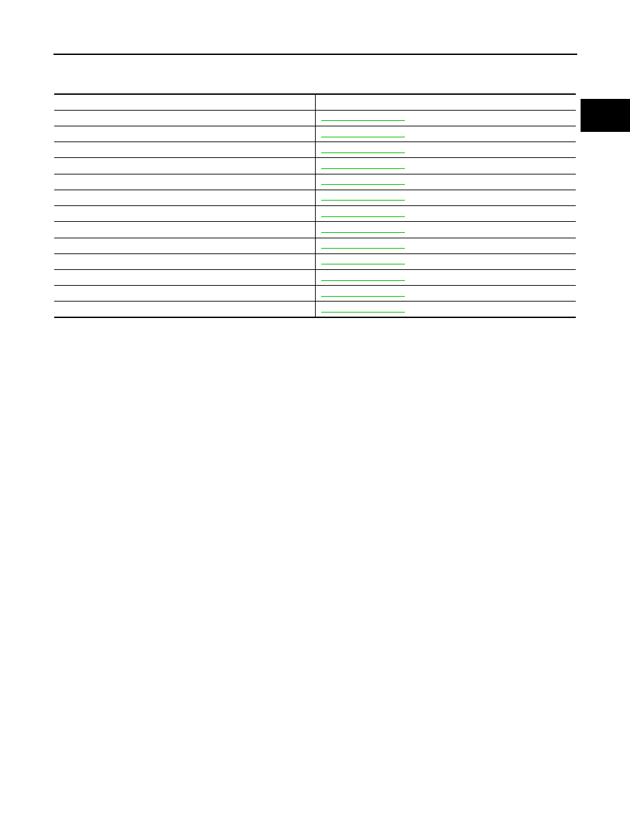
Component Description
INFOID:0000000001094056
Component
Reference
Accelerator pedal position sensor
Camshaft position sensor (PHASE)
Crankshaft position sensor (POS)
Engine coolant temperature sensor
Fuel injector
Heated oxygen sensor 1
Heated oxygen sensor 2
Intake air temperature sensor
Knock sensor
Mass air flow sensor
Park/neutral position (PNP) switch
Throttle position sensor
Vehicle speed sensor
EC-1006
< FUNCTION DIAGNOSIS >
[MR20DE (WITHOUT EURO-OBD)]
ELECTRIC IGNITION SYSTEM
ELECTRIC IGNITION SYSTEM
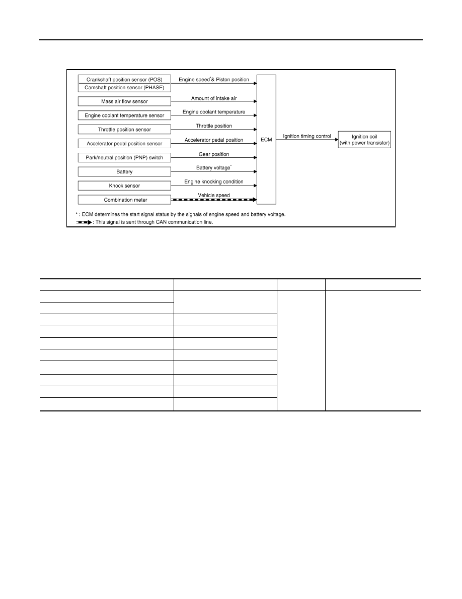
System Diagram
INFOID:0000000001094057
System Description
INFOID:0000000001094058
INPUT/OUTPUT SIGNAL CHART
*1: This signal is sent to the ECM through CAN communication line.
*2: ECM determines the start signal status by the signals of engine speed and battery voltage.
SYSTEM DESCRIPTION
Firing order: 1 - 3 - 4 - 2
The ignition timing is controlled by the ECM to maintain the best air-fuel ratio for every running condition of the
engine. The ignition timing data is stored in the ECM.
The ECM receives information such as the injection pulse width and camshaft position sensor (PHASE) sig-
nal. Computing this information, ignition signals are transmitted to the power transistor.
During the following conditions, the ignition timing is revised by the ECM according to the other data stored in
the ECM.
• At starting
• During warm-up
• At idle
• At low battery voltage
• During acceleration
The knock sensor retard system is designed only for emergencies. The basic ignition timing is programmed
within the anti-knocking zone, if recommended fuel is used under dry conditions. The retard system does not
JMBIA0174GB
Sensor
Input Signal to ECM
ECM function
Actuator
Crankshaft position sensor (POS)
Engine speed*
2
Piston position
Ignition timing
control
Ignition coil (with power transis-
tor)
Camshaft position sensor (PHASE)
Mass air flow sensor
Amount of intake air
Engine coolant temperature sensor
Engine coolant temperature
Throttle position sensor
Throttle position
Accelerator pedal position sensor
Accelerator pedal position
Battery
Battery voltage*
2
Knock sensor
Engine knocking condition
Park/neutral position (PNP) switch
Gear position
Combination meter*
1
Vehicle speed
Нет комментариевНе стесняйтесь поделиться с нами вашим ценным мнением.
Текст