Nissan Qashqai (2007-2010). Manual — part 962
INT-8
< PRECAUTION >
PRECAUTIONS
PRECAUTION
PRECAUTIONS
Precaution for Supplemental Restraint System (SRS) "AIR BAG" and "SEAT BELT
PRE-TENSIONER"
INFOID:0000000001096528
The Supplemental Restraint System such as “AIR BAG” and “SEAT BELT PRE-TENSIONER”, used along
with a front seat belt, helps to reduce the risk or severity of injury to the driver and front passenger for certain
types of collision. This system includes seat belt switch inputs and dual stage front air bag modules. The SRS
system uses the seat belt switches to determine the front air bag deployment, and may only deploy one front
air bag, depending on the severity of a collision and whether the front occupants are belted or unbelted.
Information necessary to service the system safely is included in the SRC and SB section of this Service Man-
ual.
WARNING:
• To avoid rendering the SRS inoperative, which could increase the risk of personal injury or death in
the event of a collision which would result in air bag inflation, all maintenance must be performed by
an authorized NISSAN/INFINITI dealer.
• Improper maintenance, including incorrect removal and installation of the SRS, can lead to personal
injury caused by unintentional activation of the system. For removal of Spiral Cable and Air Bag
Module, see the SRC section.
• Do not use electrical test equipment on any circuit related to the SRS unless instructed to in this
Service Manual. SRS wiring harnesses can be identified by yellow and/or orange harnesses or har-
ness connectors.
Precaution Necessary for Steering Wheel Rotation After Battery Disconnect
INFOID:0000000001096529
NOTE:
• This Procedure is applied only to models with Intelligent Key system and NATS (NISSAN ANTI-THEFT SYS-
TEM).
• Remove and install all control units after disconnecting both battery cables with the ignition knob in the
″
LOCK
″
position.
• Always use CONSULT-III to perform self-diagnosis as a part of each function inspection after finishing work.
If DTC is detected, perform trouble diagnosis according to self-diagnostic results.
For models equipped with the Intelligent Key system and NATS, an electrically controlled steering lock mech-
anism is adopted on the key cylinder.
For this reason, if the battery is disconnected or if the battery is discharged, the steering wheel will lock and
steering wheel rotation will become impossible.
If steering wheel rotation is required when battery power is interrupted, follow the procedure below before
starting the repair operation.
OPERATION PROCEDURE
1.
Connect both battery cables.
NOTE:
Supply power using jumper cables if battery is discharged.
2.
Use the Intelligent Key or mechanical key to turn the ignition switch to the
″
ACC
″
position. At this time, the
steering lock will be released.
3.
Disconnect both battery cables. The steering lock will remain released and the steering wheel can be
rotated.
4.
Perform the necessary repair operation.
5.
When the repair work is completed, return the ignition switch to the
″
LOCK
″
position before connecting
the battery cables. (At this time, the steering lock mechanism will engage.)
6.
Perform a self-diagnosis check of all control units using CONSULT-III.
Precaution for Work
INFOID:0000000001083078
• After removing and installing the opening/closing parts, be sure to carry out fitting adjustments to check their
operation.
• Check the lubrication level, damage, and wear of each part. If necessary, grease or replace it.

PREPARATION
INT-9
< PREPARATION >
C
D
E
F
G
H
I
K
L
M
A
B
INT
N
O
P
PREPARATION
PREPARATION
Commercial Service Tools
INFOID:0000000001082289
Tool name
Description
Engine ear
Location the noise
Remover tool
Remove the clips, pawls and metal clips
SIIA0995E
PIIB7923J
INT-10
< ON-VEHICLE REPAIR >
DOOR FINISHER
ON-VEHICLE REPAIR
DOOR FINISHER
FRONT DOOR FINISHER
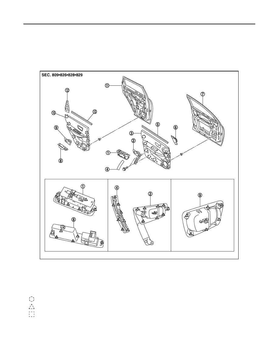
FRONT DOOR FINISHER : Exploded View
INFOID:0000000000892098
FRONT DOOR FINISHER : Removal and Installation
INFOID:0000000000892099
REMOVAL
1.
Fully open door window.
1.
Power window switch front (Driver)
2.
Front door grip
3.
Front door finisher (LH)
4.
Cap-Front door grip (LH)
5.
Seal assembly front door inside (LH) 6.
Cover front door inner (LH)
7.
Front door panel
8.
Power window switch rear (LH)
9.
Inside handle escutcheon (rear LH)
10. Rear door finisher (LH)
11. Rear door panel
12. Cover rear door inner (LH)
13. Seal assembly rear door inside (LH)
: Clip
: Pawl
: Metal clip
JMJIA0247ZZ
DOOR FINISHER
INT-11
< ON-VEHICLE REPAIR >
C
D
E
F
G
H
I
K
L
M
A
B
INT
N
O
P
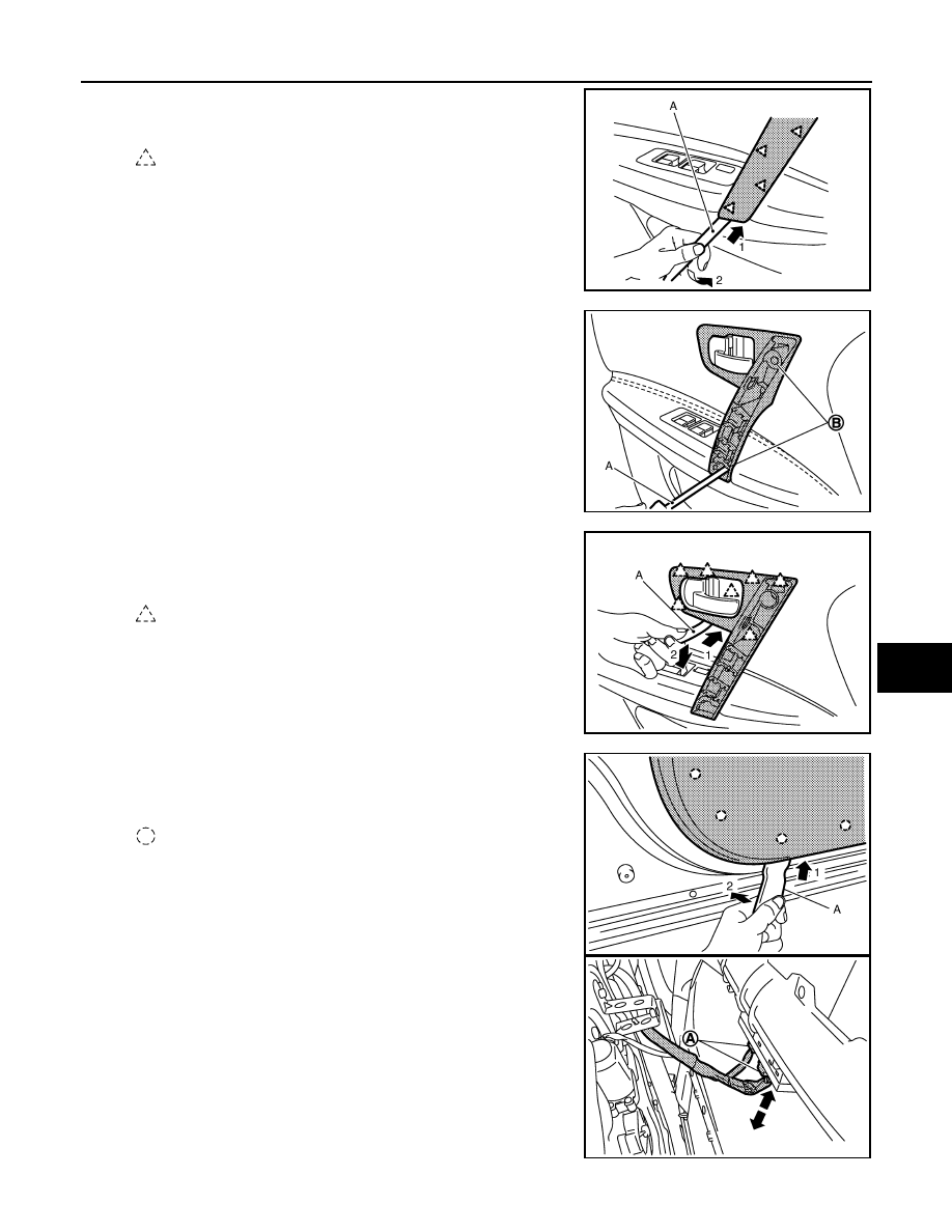
2.
Insert remover tool (A) at the bottom edge of cap-front door grip
to unclip the cap.
3.
Remove inside handle escutcheon cap.
4.
Remove screws (B) holding front door grip in place using screw-
driver (A).
5.
Hold front door grip in fully rotated position.Insert remover tool
(A) between front door grip and door finisher to disengage the
escutcheon retaining pawls to the door finisher.
6.
Remove inside handle escutcheon.
7.
Insert remover tool (A) between door finisher and door panel to
disengage door finisher mounting clips, starting from the bottom
and working to the top.
8.
Disconnect harness connectors (A) for power window switch
front.
: Pawl
JMJIA0248ZZ
JMJIA0249ZZ
: Pawl
JMJIA0250ZZ
: Clip
JMJIA0253ZZ
JMJIA0254ZZ
Нет комментариевНе стесняйтесь поделиться с нами вашим ценным мнением.
Текст