Nissan Qashqai (2007-2010). Manual — part 1129
DOOR SWITCH
DLK-595
< COMPONENT DIAGNOSIS >
[WITHOUT I-KEY & SUPER LOCK]
C
D
E
F
G
H
I
J
L
M
A
B
DLK
N
O
P
BACK DOOR
BACK DOOR : Description
INFOID:0000000001099024
Detects back door open condition.
BACK DOOR : Component Function Check
INFOID:0000000001099025
1.
CHECK FUNCTION
With CONSULT-III
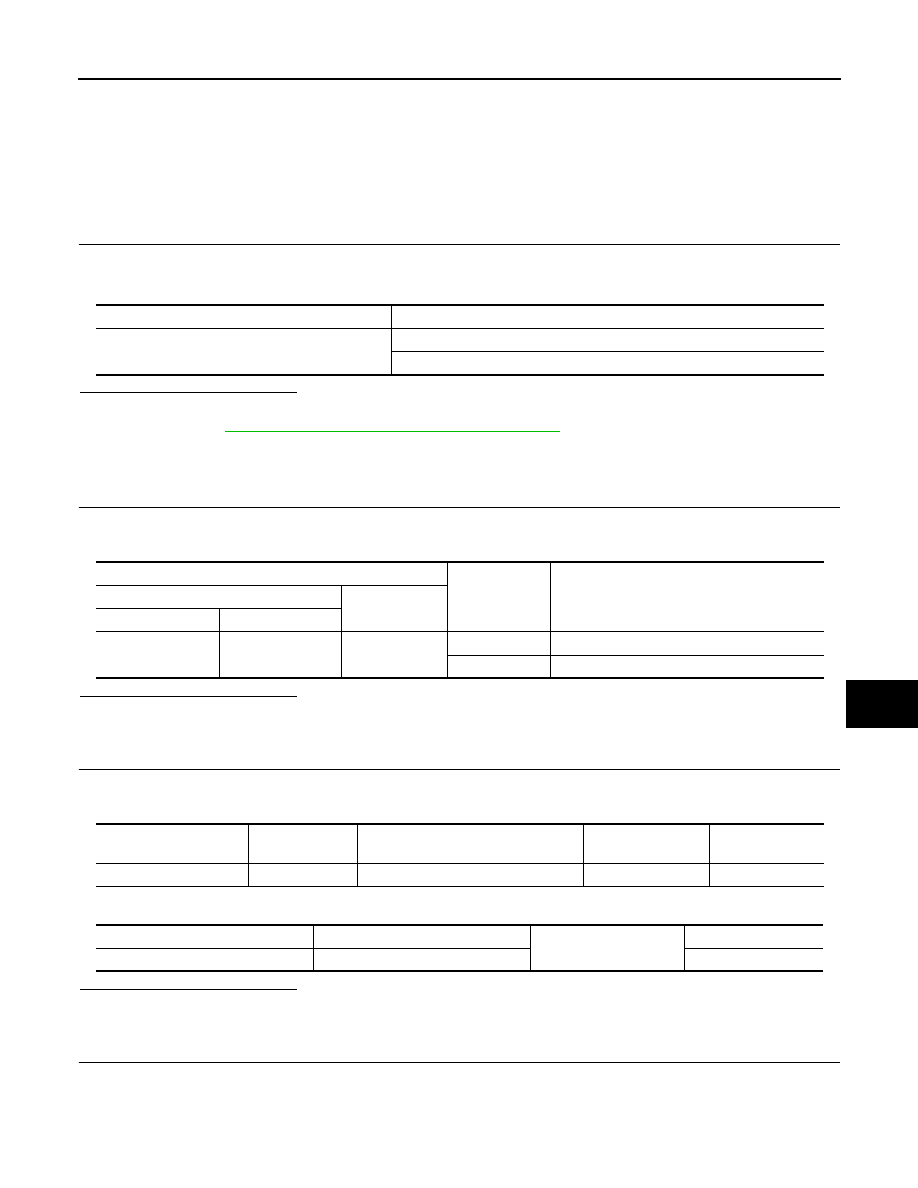
Check “BACK DOOR SW” in “Data Monitor” mode with CONSULT-III.
Is the inspection result normal?
YES
>> Back door lock assembly (door switch) is OK.
NO
>> Refer to
DLK-595, "BACK DOOR : Diagnosis Procedure"
.
BACK DOOR : Diagnosis Procedure
INFOID:0000000001099026
1.
CHECK BACK DOOR LOCK ASSEMBLY (DOOR SWITCH) INPUT SIGNAL
1.
Turn ignition switch OFF.
2.
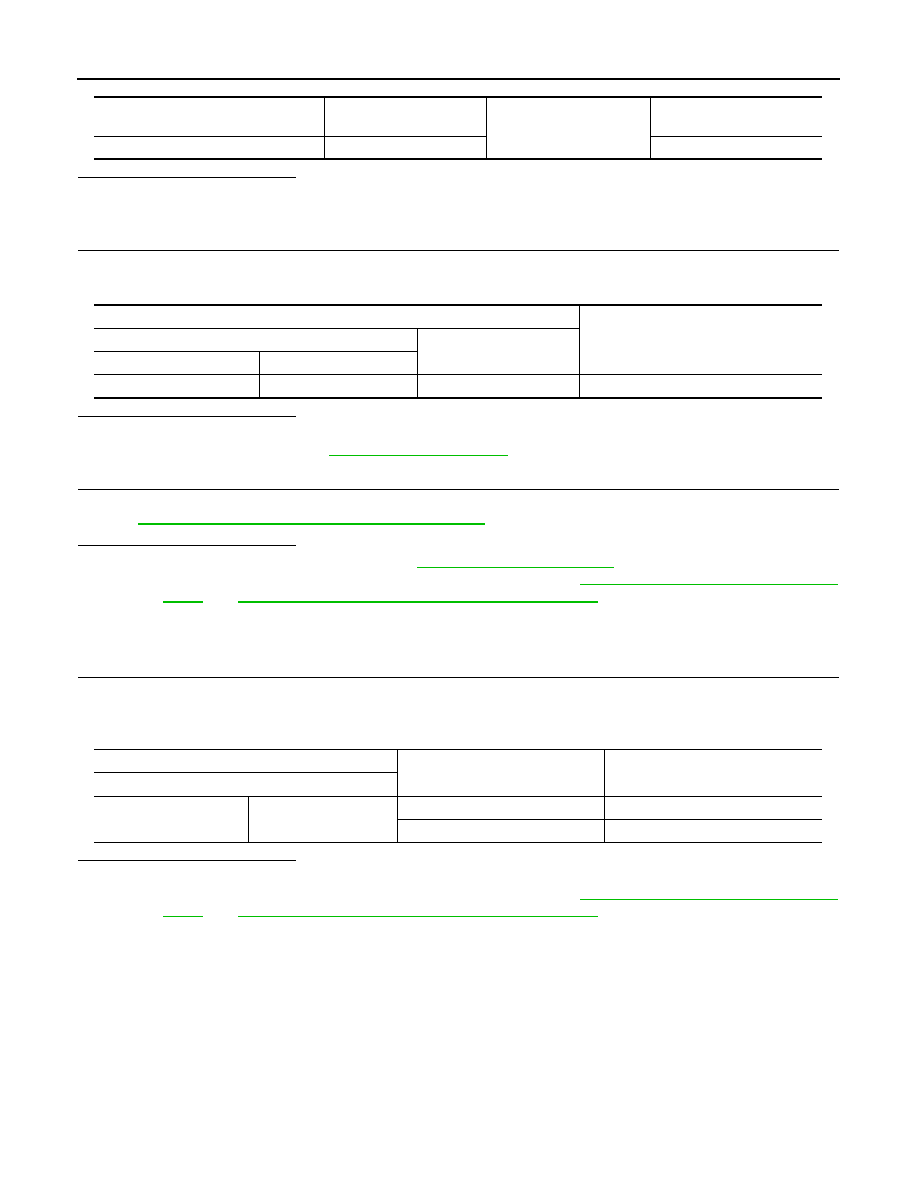
Check voltage between BCM connector and ground.
Is the inspection result normal?
YES
>> GO TO 5.
NO
>> GO TO 2.
2.
CHECK BACK DOOR LOCK ASSEMBLY (DOOR SWITCH) CIRCUIT
1.
Disconnect BCM connector.
2.
Check continuity between BCM connector and back door lock assembly (door switch) connector.
3.
Check continuity between BCM connector and ground.
Is the inspection result normal?
YES
>> GO TO 3.
NO
>> Repair or replace harness between BCM and trunk room lamp switch.
3.
CHECK BACK DOOR LOCK ASSEMBLY GROUND CIRCUIT
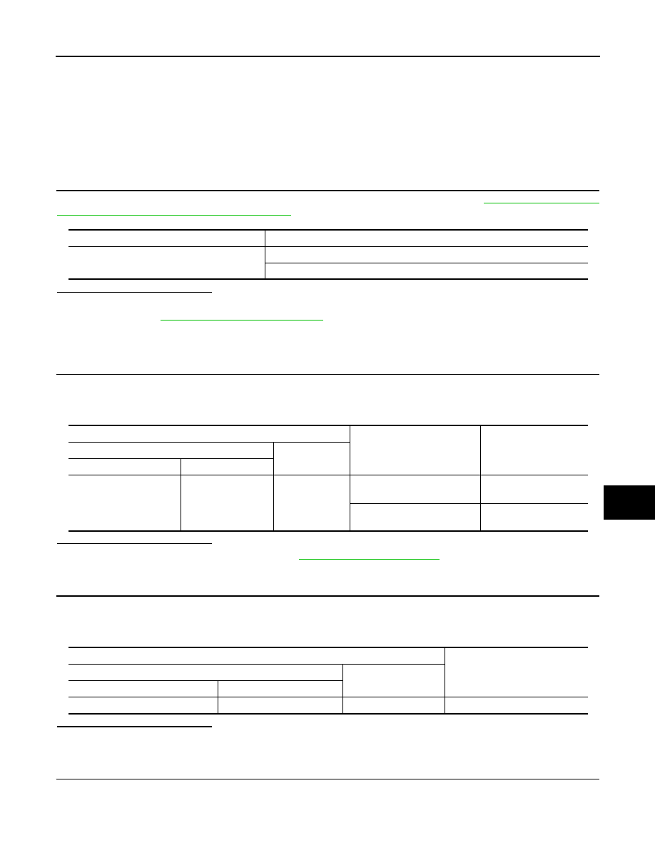
Check continuity between back door lock assembly connector and ground.
Monitor item
Condition
BACK DOOR SW
OPEN
: ON
CLOSE
: OFF
Terminals
Back door
condition
Voltage (V)
(Approx.)
(+)
(–)
BCM connector
Terminal
M65
28
Ground
OPEN
0
CLOSE
Battery voltage
BCM connector
Terminal
Back door lock assembly
(door switch) connector
Terminal
Continuity
M65
28
D152
4
Exists
BCM connector
Terminal
Ground
Continuity
M65
28
Does not exist
DLK-596
< COMPONENT DIAGNOSIS >
[WITHOUT I-KEY & SUPER LOCK]
DOOR SWITCH
Is the inspection result normal?
YES
>> GO TO 4.
NO
>> Repair or replace back door lock assembly ground circuit.
4.
CHECK BCM OUTPUT SIGNAL
1.
Connect BCM connector.
2.
Check voltage between BCM connector and ground.
Is the inspection result normal?
YES
>> GO TO 5.
NO
>> Replace BCM. Refer to
5.
CHECK BACK DOOR LOCK ASSEMBLY (DOOR SWITCH)
Check back door lock assembly (door switch).
Refer to
DLK-596, "BACK DOOR : Component Inspection"
Is the inspection result normal?
YES
>> Check intermittent incident. Refer to
GI-39, "Intermittent Incident"
.
NO
>> Replace back door lock assembly (door switch). Refer to
DLK-268, "DOOR LOCK : Exploded
DLK-268, "DOOR LOCK : Removal and Installation"
.
BACK DOOR : Component Inspection
INFOID:0000000001099027
1.
CHECK BACK DOOR LOCK ASSEMBLY (DOOR SWITCH)
1.
Turn ignition switch OFF.
2.
Disconnect back door lock assembly (door switch) connector.
3.
Check back door lock assembly (door switch).
Is the inspection result normal?
YES
>> Back door lock assembly (door switch) is OK.
NO
>> Replace back door lock assembly (door switch). Refer to
DLK-706, "DOOR LOCK : Exploded
DLK-706, "DOOR LOCK : Removal and Installation"
.
Back door lock assembly
(door switch) connector
Terminal
Ground
Continuity
D152
3
Exists
Terminals
Voltage (V)
(Approx.)
(+)
(–)
BCM connector
Terminal
M65
28
Ground
Battery voltage
Terminal
Trunk condition
Continuity
Back door lock assembly (door switch)
4
3
OPEN
Exists
CLOSE
Does not exist
KEY SWITCH
DLK-597
< COMPONENT DIAGNOSIS >
[WITHOUT I-KEY & SUPER LOCK]
C
D
E
F
G
H
I
J
L
M
A
B
DLK
N
O
P
KEY SWITCH
Description
INFOID:0000000001116382
Key switch detects that ignition key is inserted into the key cylinder, and then transmits the signal to BCM.
Component Function Check
INFOID:0000000001116383
1.
CHECK KEY SWITCH INPUT SIGNAL
Check key switch (“KEY SW”) in “DATA MONITOR” mode with CONSULT-III. Refer to
: CONSULT-III Function (BCM - DOOR LOCK)"
.
Is the inspection result normal?
YES
>> Key switch is OK.
NO
>> Refer to
DLK-597, "Diagnosis Procedure"
Diagnosis Procedure
INFOID:0000000001116384
1.
CHECK KEY SWITCH INPUT SIGNAL
1.
Turn ignition switch OFF.
2.
Disconnect BCM connector.
3.
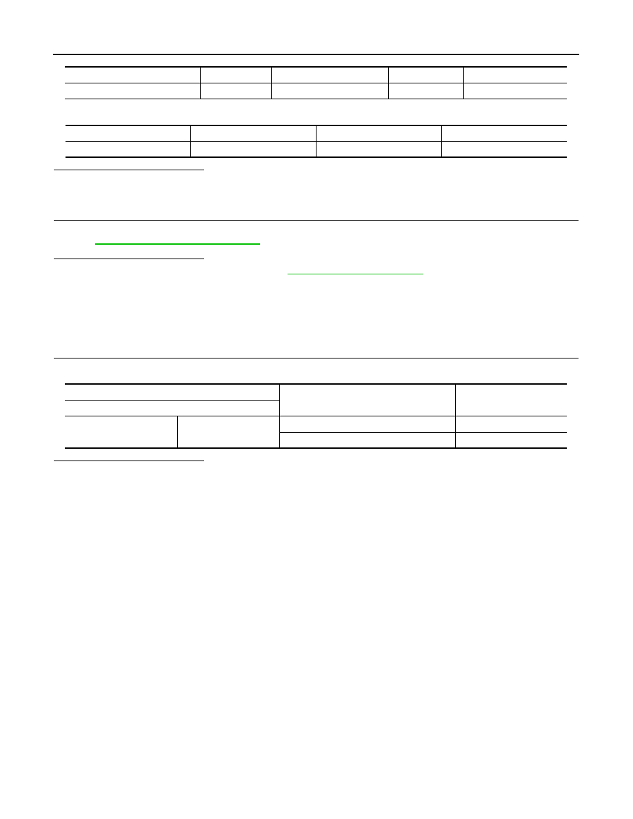
Check voltage between BCM harness connector and ground.
Is the inspection result normal?
YES
>> Check intermittent incident. Refer to
GI-39, "Intermittent Incident"
.
NO
>> GO TO 2.
2.
CHECK KEY SWITCH POWER SUPPLY CIRCUIT
1.
Remove ignition key from key cylinder.
2.
Disconnect key switch connector.
3.
Check voltage between key switch harness connector and ground.
Is the inspection result normal?
YES
>> GO TO 3.
NO
>> Repair or replace harness.
3.
CHECK KEY SWITCH SIGNAL CIRCUIT
1.
Check continuity between BCM harness connector and key switch connector.
Monitor item
Condition
KEY SW
Insert mechanical key into key cylinder
: ON
Remove mechanical key from key cylinder
: OFF
Terminals
Condition
Voltage (V)
(Approx.)
(+)
(–)
BCM connector
Terminal
M65
36
Ground
Insert ignition key into key cyl-
inder
Battery voltage
Remove ignition key from key
cylinder
0
Terminals
Voltage (V)
(Approx.)
(+)
(–)
Key switch connector
Terminal
M25
2
Ground
Battery voltage
DLK-598
< COMPONENT DIAGNOSIS >
[WITHOUT I-KEY & SUPER LOCK]
KEY SWITCH
2.
Check continuity between key switch connector and ground.
Is the inspection result normal?
YES
>> GO TO 4.
NO
>> Repair or replace harness.
4.
CHECK KEY SWITCH
Check key switch function.
Refer to
DLK-598, "Component Inspection"
.
Is the inspection result normal?
YES
>> Check intermittent incident. Refer to
GI-39, "Intermittent Incident"
.
NO
>> Replace key switch.
Component Inspection
INFOID:0000000001116385
COMPONENT INSPECTION
1.
CHECK KEY SWITCH
Check continuity between key switch terminals.
Is the inspection result normal?
YES
>> Key switch is OK.
NO
>> Replace key switch.
BCM connector
Terminal
Key switch connector
Terminal
Continuity
M65
36
M25
1
Existed
Key switch connector
Terminal
Ground
Continuity
M25
1
Ground
Not existed
Terminal
Condition
Continuity
key switch connector
1
2
Insert ignition key into key cylinder
Existed
Remove ignition key from key cylinder
Not existed
Нет комментариевНе стесняйтесь поделиться с нами вашим ценным мнением.
Текст