Nissan Qashqai (2007-2010). Manual — part 168

P0327, P0328 KS
EC-191
< COMPONENT DIAGNOSIS >
[HR16DE (WITH EURO-OBD)]
C
D
E
F
G
H
I
J
K
L
M
A
EC
N
P
O
P0327, P0328 KS
Description
INFOID:0000000001056294
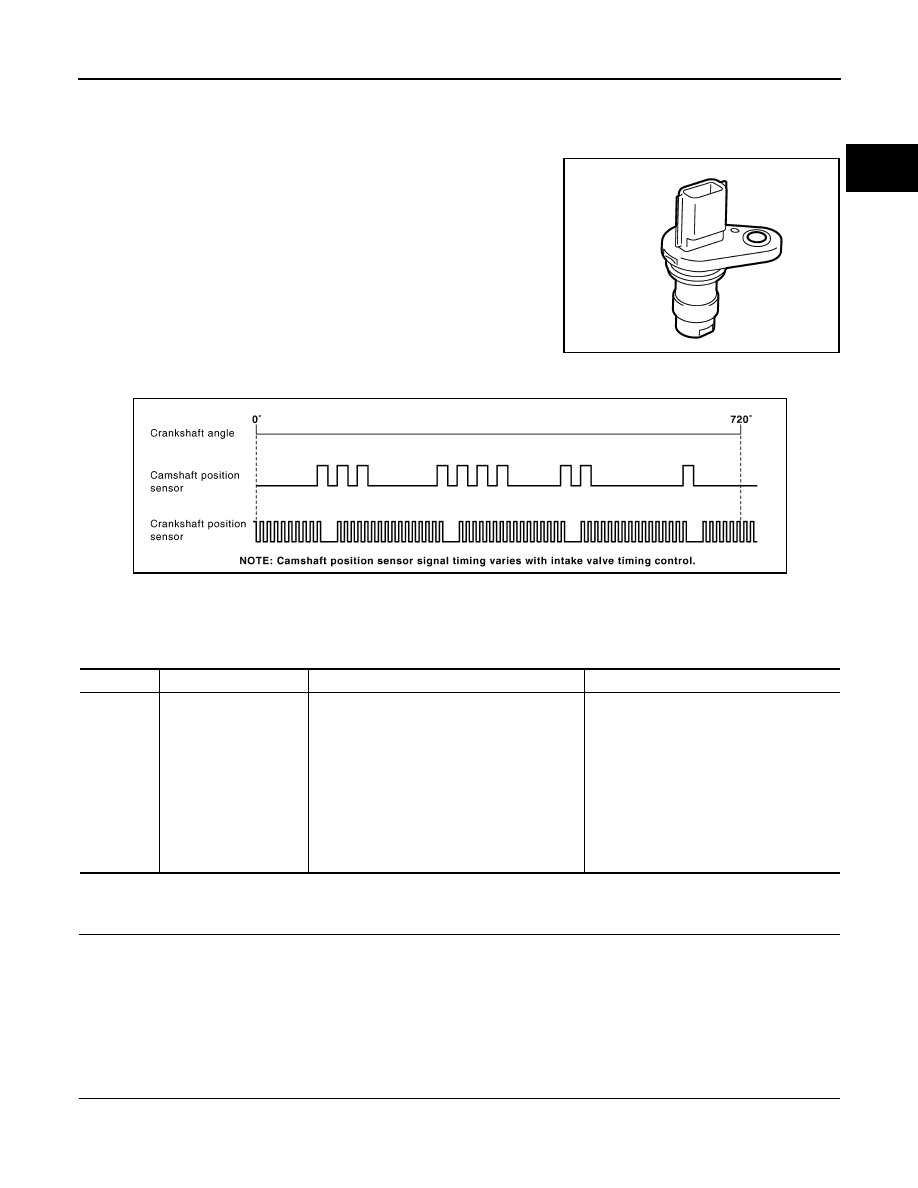
The knock sensor is attached to the cylinder block. It senses engine knocking using a piezoelectric element. A
knocking vibration from the cylinder block is sensed as vibrational pressure. This pressure is converted into a
voltage signal and sent to the ECM.
DTC Logic
INFOID:0000000001056295
DTC DETECTION LOGIC
DTC CONFIRMATION PROCEDURE
1.
PRECONDITIONING
If DTC Confirmation Procedure has been previously conducted, always turn ignition switch OFF and wait at
least 10 seconds before conducting the next test.
TESTING CONDITION:
Before performing the following procedure, confirm that battery voltage is more than 10V at idle.
>> GO TO 2.
2.
PERFORM DTC CONFIRMATION PROCEDURE
1.
Start engine and run it for at least 5 seconds at idle speed.
2.
Check 1st trip DTC.
Is 1st trip DTC detected?
YES
>> Go to
NO
>> INSPECTION END
Diagnosis Procedure
INFOID:0000000001056296
1.
CHECK GROUND CONNECTION
1.
Turn ignition switch OFF.
2.
Check ground connection E21. Refer to Ground Inspection in
.
Is the inspection result normal?
YES
>> GO TO 2.
NO
>> Repair or replace ground connection.
2.
CHECK KNOCK SENSOR GROUND CIRCUIT FOR OPEN AND SHORT
1.
Disconnect knock sensor harness connector and disconnect ECM harness connector.
2.
Check the continuity between knock sensor harness connector and ECM harness connector.
3.
Also check harness for short to ground and short to power.
Is the inspection result normal?
YES
>> GO TO 3.
NO
>> Repair open circuit or short to ground or short to power in harness or connectors.
DTC No.
Trouble diagnosis
name
DTC detected condition
Possible cause
P0327
Knock sensor circuit
low input
An excessively low voltage from the sensor is
sent to ECM.
• Harness or connectors
(The sensor circuit is open or shorted.)
• Knock sensor
P0328
Knock sensor circuit
high input
An excessively high voltage from the sensor is
sent to ECM.
Knock sensor
ECM
Continuity
Connector
Terminal
Connector
Terminal
F12
2
F8
40
Existed

EC-192
< COMPONENT DIAGNOSIS >
[HR16DE (WITH EURO-OBD)]
P0327, P0328 KS
3.
CHECK KNOCK SENSOR INPUT SIGNAL CIRCUIT FOR OPEN AND SHORT
1.
Check the continuity between knock sensor harness connector and ECM harness connector.
2.
Also check harness for short to ground and short to power.
Is the inspection result normal?
YES
>> GO TO 4.
NO
>> Repair open circuit or short to ground or short to power in harness or connectors.
4.
CHECK KNOCK SENSOR
EC-192, "Component Inspection"
Is the inspection result normal?
YES
>> GO TO 5.
NO
>> Replace knock sensor.
5.
CHECK INTERMITTENT INCIDENT
GI-39, "Intermittent Incident"
>> INSPECTION END
Component Inspection
INFOID:0000000001056297
1.
CHECK KNOCK SENSOR
1.
Turn ignition switch OFF.
2.
Disconnect knock sensor harness connector.
3.
Check resistance between knock sensor terminals as follows.
NOTE:
It is necessary to use an ohmmeter which can measure more than 10 M
Ω
.
CAUTION:
Do not use any knock sensors that have been dropped or physically damaged. Use only new ones.
Is the inspection result normal?
YES
>> INSPECTION END
NO
>> Replace knock sensor.
Knock sensor
ECM
Continuity
Connector
Terminal
Connector
Terminal
F12
1
F8
37
Existed
Terminals
Resistance [at 20
°
C (68
°
F)]
1 and 2
Approx. 532 - 588 k
Ω
P0335 CKP SENSOR (POS)
EC-193
< COMPONENT DIAGNOSIS >
[HR16DE (WITH EURO-OBD)]
C
D
E
F
G
H
I
J
K
L
M
A
EC
N
P
O
P0335 CKP SENSOR (POS)
Description
INFOID:0000000001056298
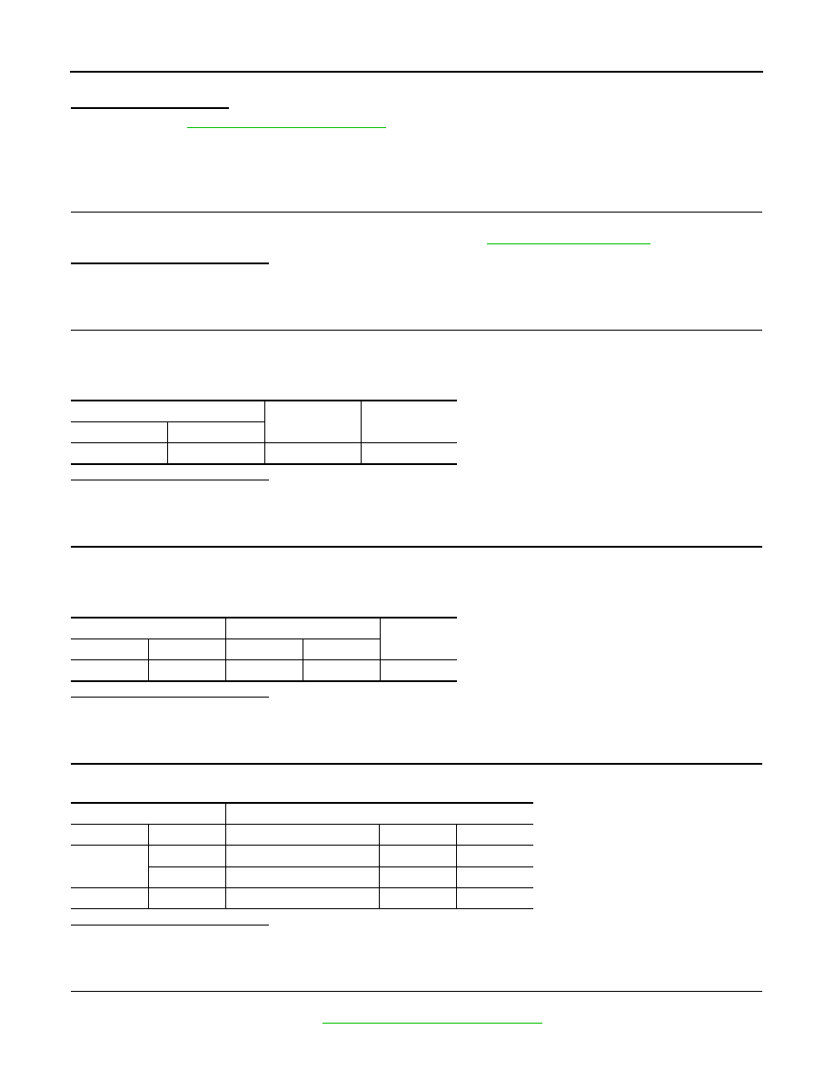
The crankshaft position sensor (POS) is located on the cylinder
block rear housing facing the gear teeth (cogs) of the signal plate at
end of the crankshaft. It detects the fluctuation of the engine revolu-
tion.
The sensor consists of a permanent magnet and Hall IC.
When the engine is running, the high and low parts of the teeth
cause the gap with the sensor to change.
The changing gap causes the magnetic field near the sensor to
change.
Due to the changing magnetic field, the voltage from the sensor
changes.
The ECM receives the voltage signal and detects the fluctuation of
the engine revolution.
ECM receives the signals as shown in the figure.
DTC Logic
INFOID:0000000001056299
DTC DETECTION LOGIC
DTC CONFIRMATION PROCEDURE
1.
PRECONDITIONING
If DTC Confirmation Procedure has been previously conducted, always turn ignition switch OFF and wait at
least 10 seconds before conducting the next test.
TESTING CONDITION:
Before performing the following procedure, confirm that battery voltage is more than 10.5V with igni-
tion switch ON.
>> GO TO 2.
2.
PERFORM DTC CONFIRMATION PROCEDURE
1.
Start engine and let it idle for at least 5 seconds.
If engine does not start, crank engine for at least 2 seconds.
PBIA9209J
PBIB2382E
DTC No.
Trouble diagnosis name
DTC detecting condition
Possible cause
P0335
Crankshaft position sen-
sor (POS) circuit
• The crankshaft position sensor (POS) signal
is not detected by the ECM during the first
few seconds of engine cranking.
• The proper pulse signal from the crankshaft
position sensor (POS) is not sent to ECM
while the engine is running.
• The crankshaft position sensor (POS) signal
is not in the normal pattern during engine run-
ning.
• Harness or connectors
[Crankshaft position sensor (POS) circuit
is open or shorted.]
(Refrigerant pressure sensor circuit is
shorted.)
(Accelerator pedal position sensor circuit
is shorted.)
• Crankshaft position sensor (POS)
• Refrigerant pressure sensor
• Accelerator pedal position sensor
• Signal plate
EC-194
< COMPONENT DIAGNOSIS >
[HR16DE (WITH EURO-OBD)]
P0335 CKP SENSOR (POS)
2.
Check 1st trip DTC.
Is 1st trip DTC detected?
YES
>> Go to
NO
>> INSPECTION END
Diagnosis Procedure
INFOID:0000000001056300
1.
CHECK GROUND CONNECTION
1.
Turn ignition switch OFF.
2.
Check ground connection E21. Refer to Ground Inspection in
.
Is the inspection result normal?
YES
>> GO TO 2.
NO
>> Repair or replace ground connection.
2.
CHECK CRANKSHAFT POSITION (CKP) SENSOR (POS) POWER SUPPLY CIRCUIT-I
1.
Disconnect crankshaft position (CKP) sensor (POS) harness connector.
2.
Turn ignition switch ON.
3.
Check the voltage between CKP sensor (POS) harness connector and ground.
Is the inspection result normal?
YES
>> GO TO 8.
NO
>> GO TO 3.
3.
CHECK CRANKSHAFT POSITION (CKP) SENSOR (POS) POWER SUPPLY CIRCUIT-II
1.
Turn ignition switch OFF.
2.
Disconnect ECM harness connector.
3.
Check the continuity between CKP sensor (POS) harness connector and ECM harness connector.
Is the inspection result normal?
YES
>> GO TO 4.
NO
>> Repair open circuit.
4.
CHECK CRANKSHAFT POSITION (CKP) SENSOR (POS) POWER SUPPLY CIRCUIT-III
Check harness for short to power and short to ground, between the following terminals.
Is the inspection result normal?
YES
>> GO TO 5.
NO
>> Repair short to ground or short to power in harness or connectors.
5.
CHECK COMPONENTS
Check the following.
• Refrigerant pressure sensor (Refer to
HAC-161, "Component Inspection"
CKP sensor (POS)
Ground
Voltage
Connector
Terminal
F20
1
Ground
Approx. 5V
CKP sensor (POS)
ECM
Continuity
Connector
Terminal
Connector
Terminal
F20
1
F8
75
Existed
ECM
Sensor
Connector
Terminal
Name
Connector
Terminal
F8
74
Refrigerant pressure sensor
E49
3
75
CKP sensor (POS)
F20
1
E16
102
APP sensor
E110
5
Нет комментариевНе стесняйтесь поделиться с нами вашим ценным мнением.
Текст