Nissan Qashqai (2007-2010). Manual — part 1939
AV-14
< COMPONENT DIAGNOSIS >
[AUDIO WITHOUT NAVIGATION]
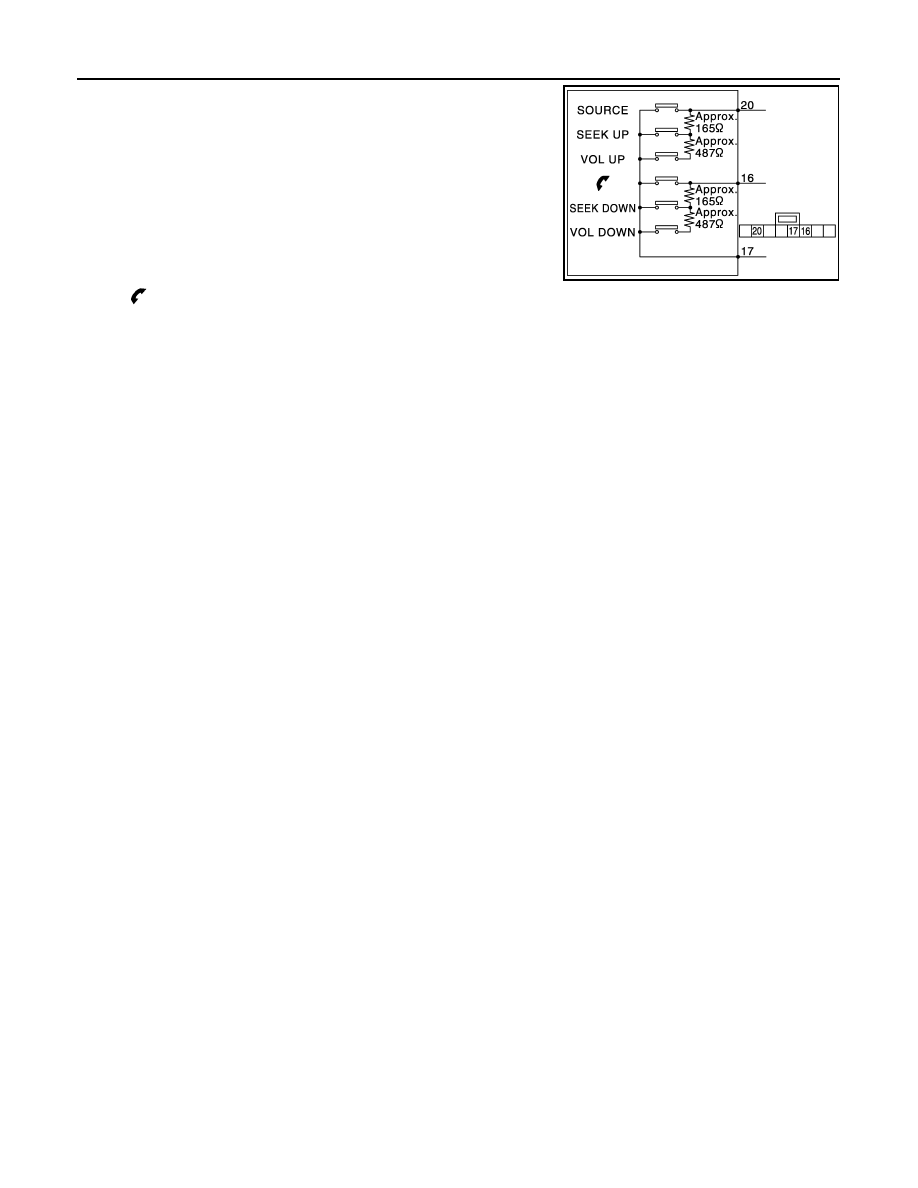
STEERING SWITCH SIGNAL B CIRCUIT
Standard
Between terminals 20 and 17
VOL UP switch ON
: 634 – 665
Ω
SEEK UP switch ON
: 162 – 168
Ω
SOURCE switch ON
: 0
Ω
Between terminals 16 and 17
VOL DOWN switch ON
: 634 – 665
Ω
SEEK DOWN switch ON
: 162 – 168
Ω
switch ON
: 0
Ω
JPNIA0167GB
AV
STEERING SWITCH SIGNAL GND CIRCUIT
AV-15
< COMPONENT DIAGNOSIS >
[AUDIO WITHOUT NAVIGATION]
C
D
E
F
G
H
I
J
K
L
M
B
A
O
P
STEERING SWITCH SIGNAL GND CIRCUIT
Description
INFOID:0000000000999576
Transmits the steering switch signal to audio unit.
Diagnosis Procedure
INFOID:0000000000996446
1.
CHECK STEERING SWITCH SIGNAL GND CIRCUIT
1.
Disconnect audio unit connector and spiral cable connector.
2.
Check continuity between audio unit harness connector terminal 15 and spiral cable harness connector
terminal 31.
3.
Connect audio unit connector.
Is inspection result OK?
YES
>> GO TO 2.
NO
>> Repair harness or connector.
2.
CHECK SPIRAL CABLE
Check spiral cable.
Is inspection result OK?
YES
>> GO TO 3.
NO
>> Replace spiral cable.
3.
CHECK GROUND CIRCUIT
1.
Connect audio unit connector.
2.
Check continuity between audio unit harness connector terminal 15 and ground.
Is inspection result OK?
YES
>> GO TO 4.
NO
>> Replace audio unit.
4.
CHECK STEERING SWITCH
1.
Turn ignition switch OFF.
2.
Check steering switch. Refer to
.
Is inspection result OK?
YES
>> INSPECTION END
NO
>> Replace steering switch.
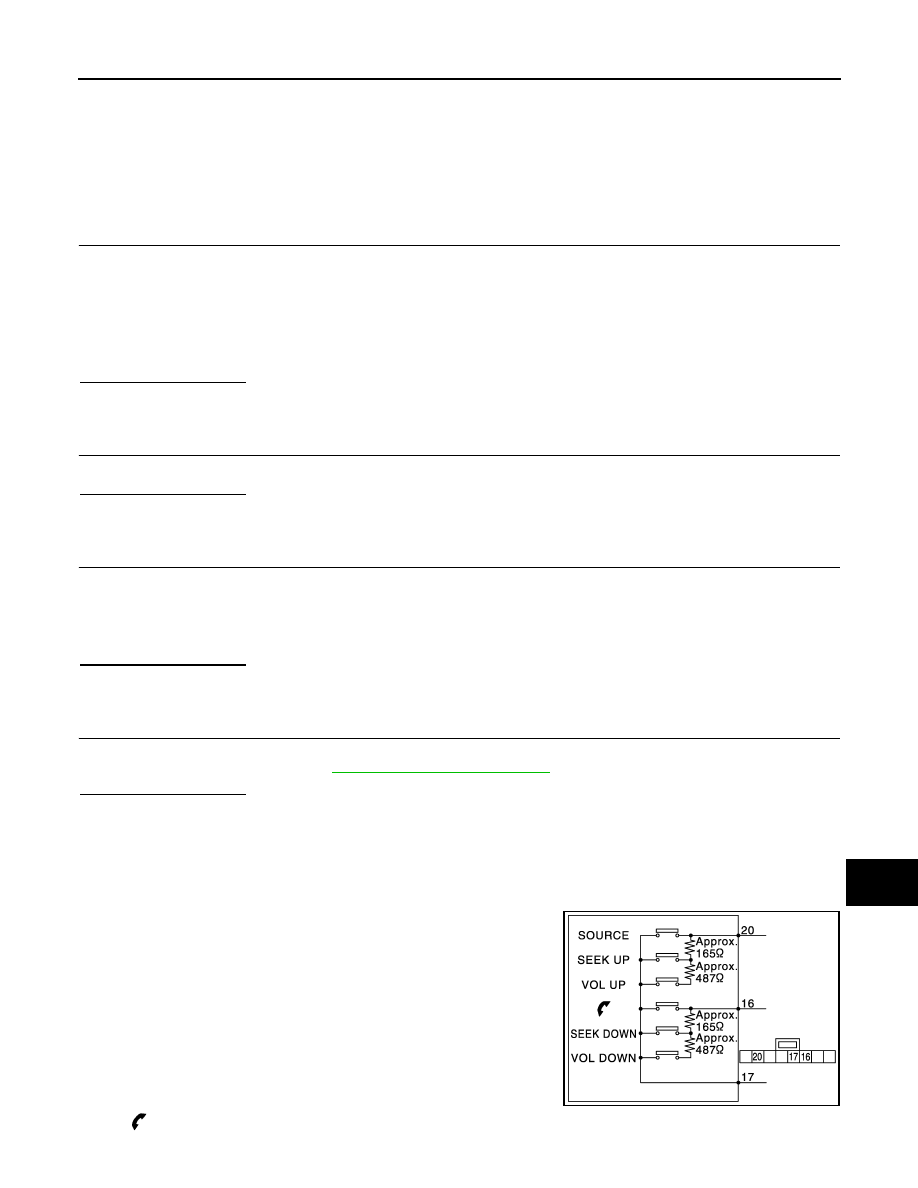
Component Inspection
INFOID:0000000000999578
Measure the resistance between the steering switch connector terminals 20 to 17 and 16 to 17.
Standard
15 - 31
: Continuity should exist.
15 - Ground
: Continuity should exist.
Between terminals 20 and 17
VOL UP switch ON
: 634 – 665
Ω
SEEK UP switch ON
: 162 – 168
Ω
SOURCE switch ON
: 0
Ω
Between terminals 16 and 17
VOL DOWN switch ON
: 634 – 665
Ω
SEEK DOWN switch ON
: 162 – 168
Ω
switch ON
: 0
Ω
JPNIA0167GB
AV-16
< ECU DIAGNOSIS >
[AUDIO WITHOUT NAVIGATION]
AUDIO UNIT
ECU DIAGNOSIS
AUDIO UNIT
Reference Value
INFOID:0000000000996452
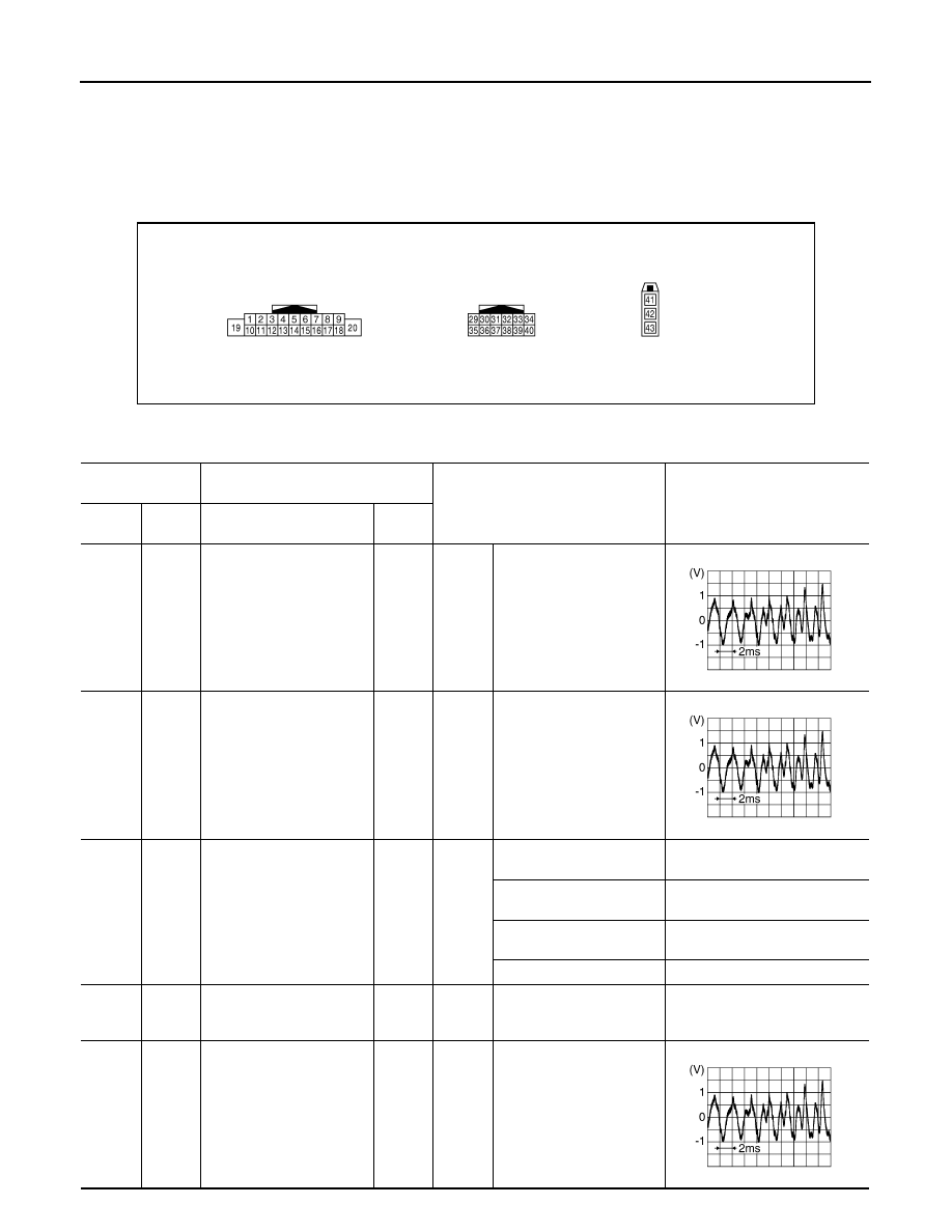
TERMINAL LAYOUT
PHYSICAL VALUES
JPNIA0230ZZ
Terminal
(Wire color)
Description
Condition
Reference value
(Approx.)
+
–
Signal name
Input/
Output
2
(L)
3
(G)
Sound signal front LH
Output
Ignition
switch
ON
Voice output
4
(LG)
5
(Y)
Sound signal rear LH
Output
Ignition
switch
ON
Voice output
6
(R)
15
(B)
Steering switch signal A
Input
Ignition
switch
ON
Keep pressing SOURCE
switch.
0 V
Keep pressing SEEK UP
switch.
1.7 V
Keep pressing VOL UP
switch.
3.3 V
Except for above.
5 V
7
(R)
Ground
ACC power supply
Input
Ignition
switch
ACC
−
Battery voltage
11
(BR)
12
(P)
Sound signal front RH
Output
Ignition
switch
ON
Voice output
SKIB3609E
SKIB3609E
SKIB3609E
AV
AUDIO UNIT
AV-17
< ECU DIAGNOSIS >
[AUDIO WITHOUT NAVIGATION]
C
D
E
F
G
H
I
J
K
L
M
B
A
O
P
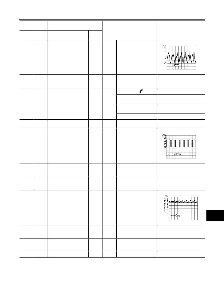
13
(O)
14
(V)
Sound signal rear RH
Output
Ignition
switch
ON
Voice output
15
(B)
Ground
Steering switch signal GND
—
Ignition
switch
ON
—
0 V
16
(Y)
15
(B)
Steering switch signal B
Input
Ignition
switch
ON
Keep pressing
switch.
0 V
Keep pressing SEEK
DOWN switch.
1.7 V
Keep pressing VOL DOWN
switch.
3.3 V
Except for above.
5 V
17
(SB)
—
Immobilizer
—
—
—
—
18
(Y)
Ground
Vehicle speed signal (8-
pulse)
Input
Ignition
switch
ON
When vehicle speed is ap-
prox. 40 km/h (25MPH)
19
(LG)
Ground
Battery power supply
Input
Ignition
switch
OFF
—
Battery voltage
31
(B)
Ground
GND
—
Ignition
switch
ON
—
0 V
35
(B/W)
36
Microphone signal
Input
Ignition
switch
ON
Sounds
36
Ground
Microphone GND
—
Ignition
switch
ON
—
0 V
37
(L)
36
Microphone VCC
Output
Ignition
switch
ON
—
5 V
42
—
Antenna signal
Input
—
—
—
Terminal
(Wire color)
Description
Condition
Reference value
(Approx.)
+
–
Signal name
Input/
Output
SKIB3609E
SKIA6649J
PKIB5037J
Нет комментариевНе стесняйтесь поделиться с нами вашим ценным мнением.
Текст