Nissan Qashqai (2007-2010). Manual — part 1859
CHG-8
< FUNCTION DIAGNOSIS >
CHARGING SYSTEM
FUNCTION DIAGNOSIS
CHARGING SYSTEM
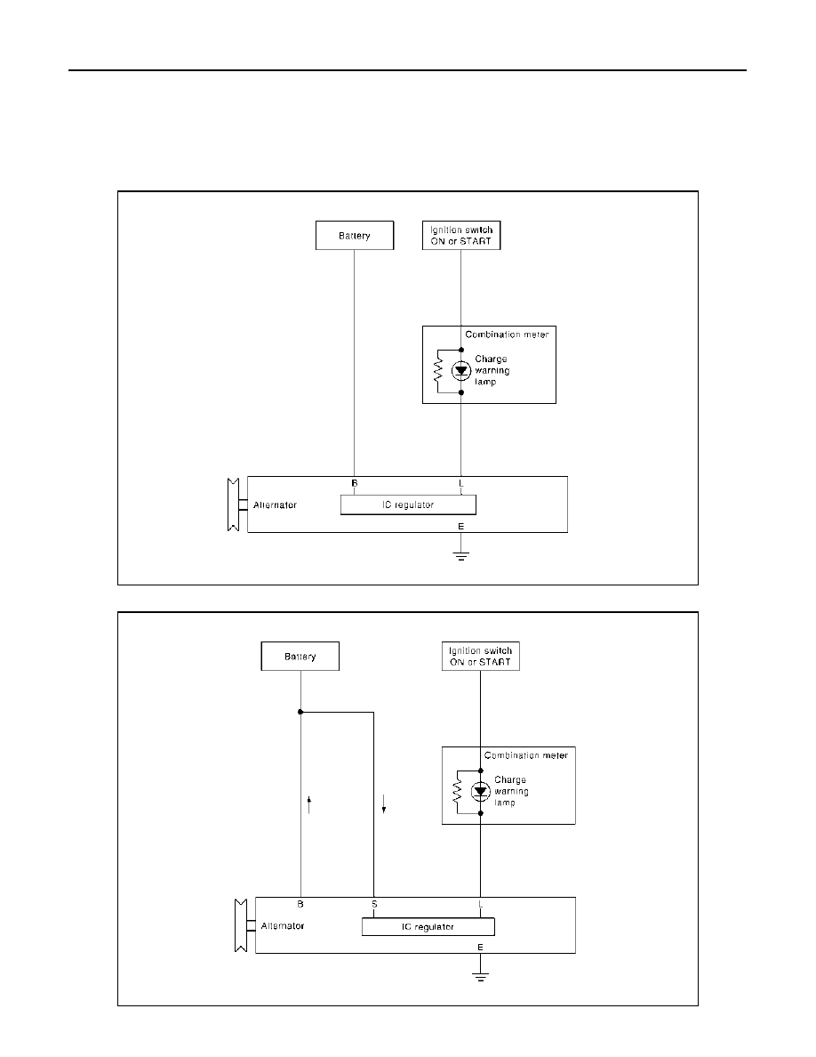
System Diagram
INFOID:0000000000955235
K9K models
HR16DE/MR20DE models
JPMIA0250GB
JPMIA0238GB
CHG
CHARGING SYSTEM
CHG-9
< FUNCTION DIAGNOSIS >
C
D
E
F
G
H
I
J
K
L
B
A
O
P
N
System Description
INFOID:0000000000955236
The alternator provides DC voltage to operate the vehicle's electrical system and to keep the battery charged.
The voltage output is controlled by the IC regulator.
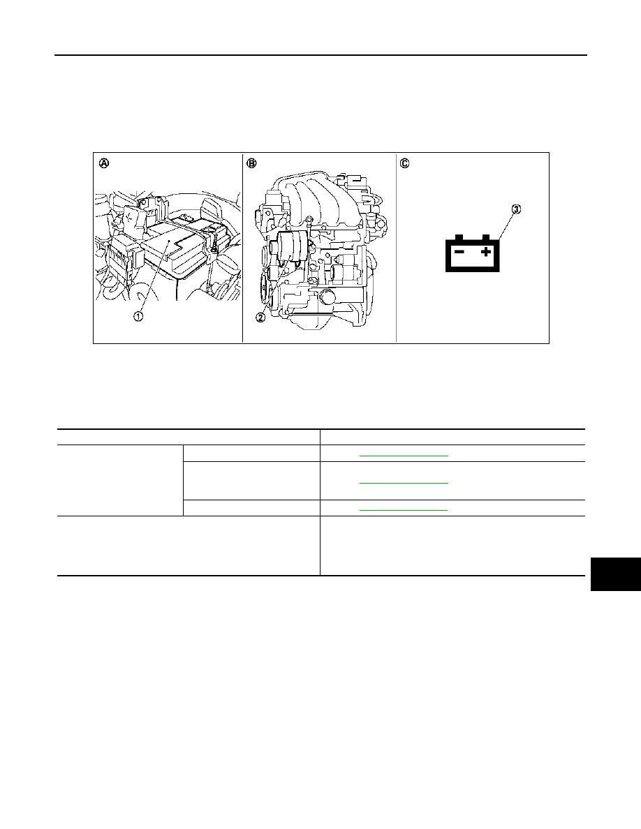
Component Parts Location
INFOID:0000000000955237
Component Description
INFOID:0000000000955238
1.
Battery
2.
Alternator
3.
Charge warning lamp
A.
Engine room (left side)
B.
Engine
C.
Combination meter
JPMIA0225ZZ
Component part
Description
Alternator
“B” terminal
“S” terminal
(HR16DE/MR20DE models
only)
“L” terminal
Combination meter (Charge warning lamp)
The IC regulator warning function activates to illuminate the
charge warning lamp, if any of the following symptoms occur while
alternator is operating:
• Excessive voltage is produced.
• No voltage is produced.
CHG-10
< COMPONENT DIAGNOSIS >
B TERMINAL CIRCUIT
COMPONENT DIAGNOSIS
B TERMINAL CIRCUIT
Description
INFOID:0000000000955243
“B” terminal circuit supplies power to charge the battery and to operate the vehicle’s electrical system.
Diagnosis Procedure
INFOID:0000000000955244
1.
CHECK “B” TERMINAL CONNECTION
1.
Turn ignition switch OFF.
2.
Check if “B” terminal is clean and tight.
Is the inspection result normal?
YES
>> GO TO 2.
NO
>> Repair “B” terminal connection.
2.
CHECK “B” TERMINAL CIRCUIT
Check voltage between alternator “B” terminal and ground.
Is the inspection result normal?
YES
>> GO TO 3.
NO
>> Check harness for open between alternator and fusible link.
3.
CHECK “B” TERMINAL CONNECTION (VOLTAGE DROP TEST)
1.
Start engine, then engine running at idle and warm.
2.
Check voltage between battery positive terminal and alternator “B” terminal.
Is the inspection result normal?
YES
>> “B” terminal circuit is normal. Refer to
CHG-3, "K9K MODELS : Work Flow"
CHG-4, "HR16DE/MR20DE MODELS : Work Flow"
NO
>> Check harness between battery and alternator for poor continuity.
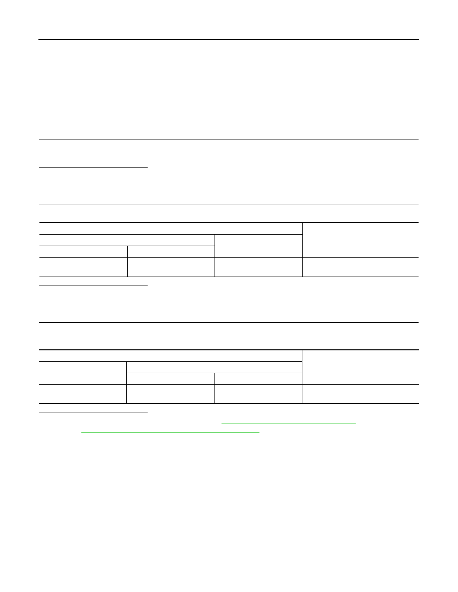
Terminals
Voltage (Approx.)
(+)
(–)
Alternator “B” terminal
Terminal
F59 (K9K)
F14 (HR16DE/MR20DE)
1
Ground
Battery voltage
Terminals
Voltage (Approx.)
(+)
(–)
Alternator “B” terminal
Terminal
Battery positive terminal
F59 (K9K)
F14 (HR16DE/MR20DE)
1
Less than 0.2 V
CHG
L TERMINAL CIRCUIT (OPEN)
CHG-11
< COMPONENT DIAGNOSIS >
C
D
E
F
G
H
I
J
K
L
B
A
O
P
N
L TERMINAL CIRCUIT (OPEN)
Description
INFOID:0000000000955245
The “L” terminal circuit controls the charge warning lamp. The charge warning lamp illuminates when the igni-
tion switch is set to ON or START. When the alternator is providing sufficient voltage with the engine running,
the charge warning lamp will go off. If the charge warning lamp illuminates with the engine running, a malfunc-
tion is indicated.
Diagnosis Procedure
INFOID:0000000000955246
1.
CHECK “L” TERMINAL CONNECTION
1.
Turn ignition switch OFF.
2.
Check if “L” terminal is clean and tight.
Is the inspection result normal?
YES
>> GO TO 2.
NO
>> Repair “L” terminal connection.
2.
CHECK “L” TERMINAL CIRCUIT (OPEN)
1.
Disconnect alternator connector.
2.
Apply ground to alternator connector harness connector terminal.
3.
Check condition of the charge warning lamp with the ignition switch in the ON position.
-
K9K models
-
HR16DE/MR20DE models
Does it illuminate?
YES
>> “L” terminal circuit is normal. Refer to
CHG-3, "K9K MODELS : Work Flow"
(K9K models) or
4, "HR16DE/MR20DE MODELS : Work Flow"
(HR16DE/MR20DE models).
NO
>> GO TO 3.
3.
CHECK HARNESS CONTINUITY (OPEN CIRCUIT)
1.
Disconnect the battery cable from the negative terminal.
2.
Disconnect the combination meter connector.
3.
Check continuity between alternator harness connector and combination meter harness connector.
-
K9K engine models
-
HR engine/MR engine models
Is the inspection result normal?
YES
>> GO TO 4.
NO
>> Repair the harness or connector.
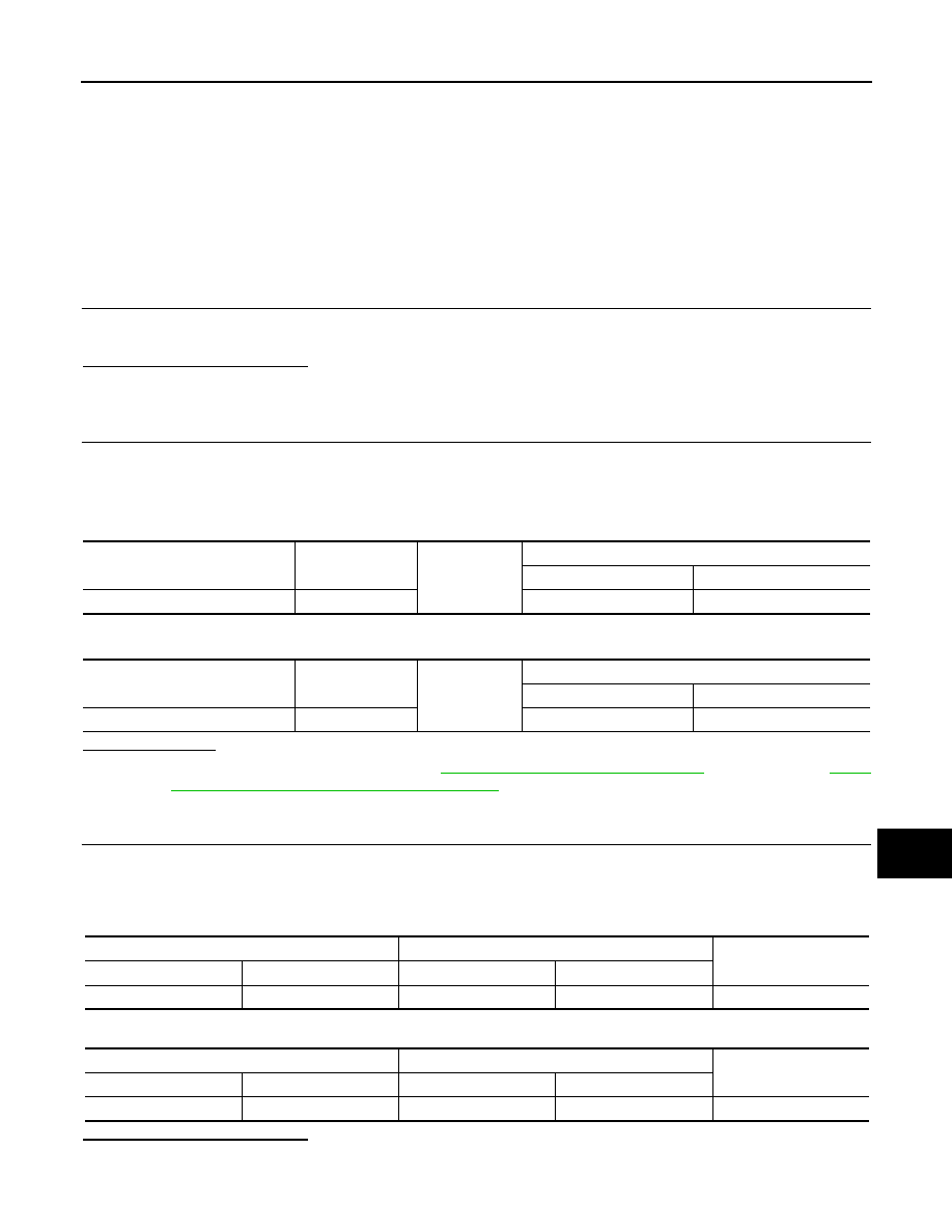
Alternator harness connector
Terminal
Ground
Condition
Ignition switch position
Charge warning lamp
F60
4
ON
Illuminate
Alternator harness connector
Terminal
Ground
Condition
Ignition switch position
Charge warning lamp
F15
3
ON
Illuminate
Alternator harness connector
Combination meter harness connector
Continuity
Connector No.
Terminal No.
Connector No.
Terminal No.
F60
4
M34
25
Existed
Alternator harness connector
Combination meter harness connector
Continuity
Connector No.
Terminal No.
Connector No.
Terminal No.
F15
3
M34
25
Existed
Нет комментариевНе стесняйтесь поделиться с нами вашим ценным мнением.
Текст