Nissan Qashqai (2007-2010). Manual — part 327
P1111 IVT CONTROL SOLENOID VALVE
EC-827
< COMPONENT DIAGNOSIS >
[MR20DE (WITH EURO-OBD)]
C
D
E
F
G
H
I
J
K
L
M
A
EC
N
P
O
P1111 IVT CONTROL SOLENOID VALVE
Description
INFOID:0000000001089402
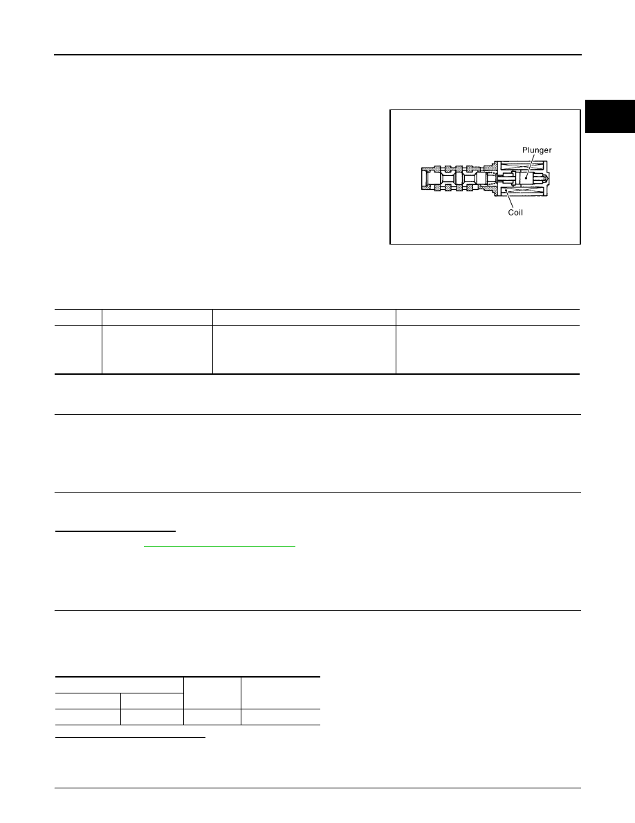
Intake valve timing control solenoid valve is activated by ON/OFF
pulse duty (ratio) signals from the ECM.
The intake valve timing control solenoid valve changes the oil
amount and direction of flow through intake valve timing control unit
or stops oil flow.
The longer pulse width advances valve angle.
The shorter pulse width retards valve angle.
When ON and OFF pulse widths become equal, the solenoid valve
stops oil pressure flow to fix the intake valve angle at the control
position.
DTC Logic
INFOID:0000000001089403
DTC DETECTION LOGIC
DTC CONFIRMATION PROCEDURE
1.
PRECONDITIONING
If DTC Confirmation Procedure has been previously conducted, always turn ignition switch OFF and wait at
least 10 seconds before conducting the next test.
>> GO TO2.
2.
PERFORM DTC CONFIRMATION PROCEDURE
1.
Start engine and let it idle for 5 seconds.
2.
Check 1st trip DTC.
Is 1st trip DTC detected?
YES
>> Go to
NO
>> INSPECTION END
Diagnosis Procedure
INFOID:0000000001089404
1.
CHECK INTAKE VALVE TIMING CONTROL SOLENOID VALVE POWER SUPPLY CIRCUIT
1.
Turn ignition switch OFF.
2.
Disconnect intake valve timing control solenoid valve harness connector.
3.
Turn ignition switch ON.
4.
Check the voltage between intake valve timing control solenoid valve harness connector and ground.
Is the inspection result normal?
YES
>> GO TO 3.
NO
>> GO TO 2.
2.
DETECT MALFUNCTION PART
PBIB1842E
DTC No.
Trouble diagnosis name
DTC detecting condition
Possible cause
P1111
Intake valve timing control
solenoid valve circuit
An improper voltage is sent to the ECM
through intake valve timing control solenoid
valve.
• Harness or connectors
(Intake valve timing control solenoid valve
circuit is open or shorted.)
• Intake valve timing control solenoid valve
IVT control solenoid valve
Ground
Voltage
Connector
Terminal
F41
2
Ground
Battery voltage

EC-828
< COMPONENT DIAGNOSIS >
[MR20DE (WITH EURO-OBD)]
P1111 IVT CONTROL SOLENOID VALVE
Check the following.
• Harness connectors E7, F121
• Harness for open or short between intake valve timing control solenoid valve and IPDM E/R
>> Repair or replace harness or connectors.
3.
CHECK INTAKE VALVE TIMING CONTROL SOLENOID VALVE OUTPUT SIGNAL CIRCUIT FOR OPEN
AND SHORT
1.
Turn ignition switch OFF.
2.
Disconnect ECM harness connector.
3.
Check the continuity between intake valve timing control solenoid valve harness connector and ECM har-
ness connector.
4.
Also check harness for short to ground and short to power.
Is the inspection result normal?
YES
>> GO TO 4.
NO
>> Repair open circuit or short to ground or short to power in harness or connectors.
4.
CHECK INTAKE VALVE TIMING CONTROL SOLENOID VALVE
EC-830, "Component Inspection"
Is the inspection result normal?
YES
>> GO TO 5.
NO
>> Replace intake valve timing control solenoid valve.
5.
CHECK INTERMITTENT INCIDENT
GI-39, "Intermittent Incident"
>> INSPECTION END
Component Inspection
INFOID:0000000001089405
1.
CHECK INTAKE VALVE TIMING CONTROL SOLENOID VALVE-I
1.
Turn ignition switch OFF.
2.
Disconnect intake valve timing control solenoid valve harness connector.
3.
Check resistance between intake valve timing control solenoid valve terminals as follows.
Is the inspection result normal?
YES
>> GO TO 2.
NO
>> Replace intake valve timing control solenoid valve.
2.
CHECK INTAKE VALVE TIMING CONTROL SOLENOID VALVE-II
1.
Remove intake valve timing control solenoid valve.
IVT control solenoid valve
ECM
Continuity
Connector
Terminal
Connector
Terminal
F41
1
F8
73
Existed
Terminals
Resistance [at 20
°
C (68
°
F)]
1 and 2
6.7 - 7.7
Ω
1 or 2 and ground
∞
Ω
(Continuity should not exist)
P1111 IVT CONTROL SOLENOID VALVE
EC-829
< COMPONENT DIAGNOSIS >
[MR20DE (WITH EURO-OBD)]
C
D
E
F
G
H
I
J
K
L
M
A
EC
N
P
O
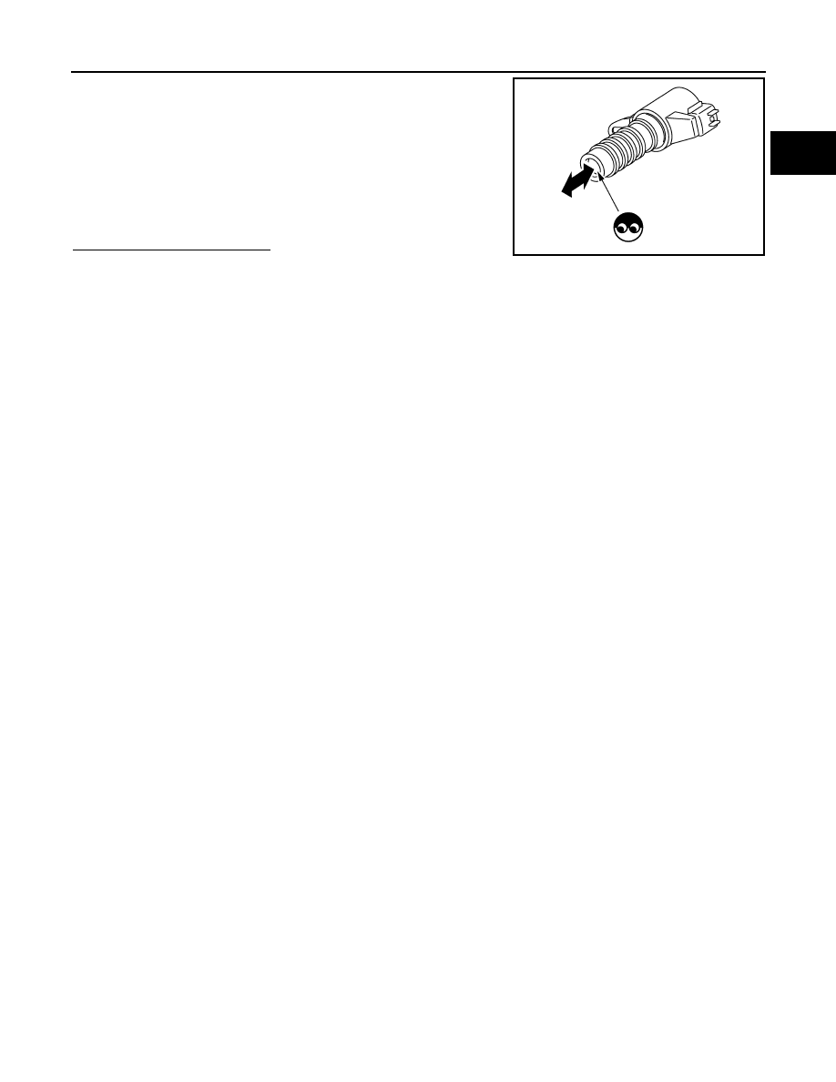
2.
Provide 12V DC between intake valve timing control solenoid
valve terminals 1 and 2, and then interrupt it. Make sure that the
plunger moves as shown in the figure.
CAUTION:
Do not apply 12V DC continuously for 5 seconds or more.
Doing so may result in damage to the coil in intake valve
timing control solenoid valve.
NOTE:
Always replace O-ring when intake valve timing control
solenoid valve is removed.
Is the inspection result normal?
YES
>> INSPECTION END
NO
>> Replace intake valve timing control solenoid valve.
JMBIA0350ZZ

EC-830
< COMPONENT DIAGNOSIS >
[MR20DE (WITH EURO-OBD)]
P1121 ELECTRIC THROTTLE CONTROL ACTUATOR
P1121 ELECTRIC THROTTLE CONTROL ACTUATOR
Description
INFOID:0000000001089406
Electric throttle control actuator consists of throttle control motor, throttle position sensor, etc.
The throttle control motor is operated by the ECM and it opens and closes the throttle valve.
The throttle position sensor detects the throttle valve position, and the opening and closing speed of the throt-
tle valve and feeds the voltage signals to the ECM. The ECM judges the current opening angle of the throttle
valve from these signals and the ECM controls the throttle control motor to make the throttle valve opening
angle properly in response to driving condition.
DTC Logic
INFOID:0000000001089407
DTC DETECTION LOGIC
DTC CONFIRMATION PROCEDURE
1.
PRECONDITIONING
If DTC Confirmation Procedure has been previously conducted, always turn ignition switch OFF and wait at
least 10 seconds before conducting the next test.
>> GO TO 2.
2.
PERFORM DTC CONFIRMATION PROCEDURE FOR MALFUNCTION A AND B
1.
Turn ignition switch ON and wait at least 1 second.
2.
Set shift lever to D (CVT) or 1st (M/T) position and wait at least 3 seconds.
3.
Set shift lever to P (CVT) or Neutral (M/T) position.
4.
Turn ignition switch OFF and wait at least 10 seconds.
5.
Turn ignition switch ON and wait at least 1 second.
6.
Set shift lever to D (CVT) or 1st (M/T) position and wait at least 3 seconds.
7.
Set shift lever to P (CVT) or Neutral (M/T) position.
8.
Turn ignition switch OFF, wait at least 10 seconds, and then turn ON.
9.
Check DTC.
Is DTC detected?
YES
>> Go to
NO
>> GO TO 3.
3.
PERFORM DTC CONFIRMATION PROCEDURE FOR MALFUNCTION C
1.
Turn ignition switch ON and wait at least 1 second.
2.
Set shift lever to D (CVT) or 1st (M/T) position and wait at least 3 seconds.
3.
Set shift lever to N, P (CVT) or Neutral (M/T) position.
4.
Start engine and let it idle for 3 seconds.
5.
Check DTC.
Is DTC detected?
YES
>> Go to
NO
>> INSPECTION END
Diagnosis Procedure
INFOID:0000000001089408
1.
CHECK ELECTRIC THROTTLE CONTROL ACTUATOR VISUALLY
DTC No.
Trouble diagnosis name
DTC detecting condition
Possible cause
P1121
Electric throttle control
actuator
A)
Electric throttle control actuator does not func-
tion properly due to the return spring malfunc-
tion.
• Electric throttle control actuator
B)
Throttle valve opening angle in fail-safe mode is
not in specified range.
C)
ECM detect the throttle valve is stuck open.
Нет комментариевНе стесняйтесь поделиться с нами вашим ценным мнением.
Текст