Nissan Qashqai (2007-2010). Manual — part 841
BLOWER MOTOR
VTL-29
< ON-VEHICLE REPAIR >
[AUTOMATIC AIR CONDITIONER]
C
D
E
F
G
H
J
K
L
M
A
B
VTL
N
O
P
BLOWER MOTOR
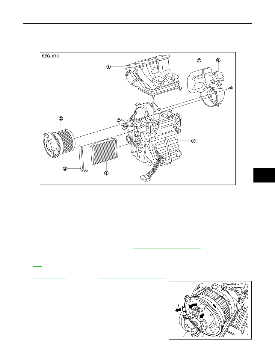
Exploded View
INFOID:0000000001093716
Removal and Installation
INFOID:0000000001093717
REMOVAL
LHD MODEL
1.
Remove driver lower instrument panel. Refer to
IP-12, "Removal and Installation"
.
2.
Remove driver foot duct fixing screw, and remove it.
3.
Remove accelerator pedal, and disconnect harness connector. Refer to
4.
Remove brake and clutch pedal assembly, disconnect harness connectors. Refer to
CL-8, "Removal and Installation"
5.
Remove blower motor harness connector.
6.
Remove motor fixing screw, then remove blower motor.
7.
Remove blower motor assembly, as shown.
• Remove fixing screw.
• Disconnect harness connector (A).
• Release maintaining pawl (1) then turn counter clockwise (2)
blower motor assembly.
• Pull outside (3) and remove it.
CAUTION:
Take care of harness connectors around blower motor.
1.
Hi-Level ventilation door unit assem-
bly
2.
Blower motor assembly
3.
Filter cover
4.
In-cabin microfilter
5.
Blower unit
6.
Intake door motor
7.
Intake door unit assembly
E1IIA0002GB
E1IIA0009ZZ
VTL-30
< ON-VEHICLE REPAIR >
[AUTOMATIC AIR CONDITIONER]
BLOWER MOTOR
RHD MODEL
1.
Remove passenger lower instrument panel. Refer to
IP-12, "Removal and Installation"
.
2.
Remove glove Box.
3.
Remove passenger foot duct fixing screw, and remove it.
4.
Remove glove box duct fixing screw, and remove it.
5.
Remove BCM unit. Refer to
BCS-64, "Removal and Installation"
6.
Remove blower motor harness connector.
7.
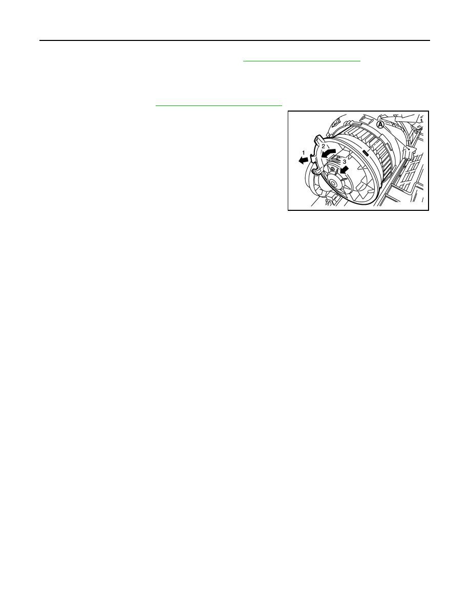
Remove blower motor assembly, as shown
8.
Remove fixing screw.
• Disconnect harness connector (A).
• Release maintaining pawl (1) then turn counter clockwise (2)
blower motor assembly.
• Pull outside (3) and remove it.
CAUTION:
Take care of harness connectors around blower motor.
INSTALLATION
Installation is basically the reverse order of removal.
E1IIA0009ZZ
INTAKE DOOR MOTOR
VTL-31
< ON-VEHICLE REPAIR >
[AUTOMATIC AIR CONDITIONER]
C
D
E
F
G
H
J
K
L
M
A
B
VTL
N
O
P
INTAKE DOOR MOTOR
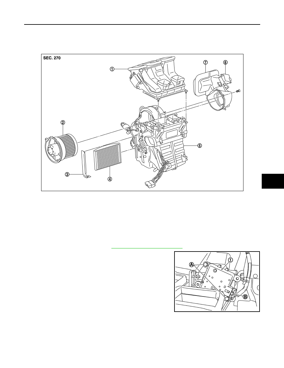
Exploded View
INFOID:0000000001093718
Removal and Installation
INFOID:0000000001093719
REMOVAL
1.
Remove Instrument Panel. Refer to
IP-12, "Removal and Installation"
2.
Disconnect intake door motor connector (B).
3.
Remove harness connector fixing clip.
4.
Remove intake door motor fixing screws (A).
5.
Remove intake door motor (1).
INSTALLATION
Installation is basically the reverse order of removal.
1.
Hi-Level ventilation door unit assem-
bly
2.
Blower motor assembly
3.
Filter cover
4.
In-cabin microfilter
5.
Blower unit
6.
Intake door motor
7.
Intake door unit assembly
E1IIA0002GB
E1IIA0017ZZ
VTL-32
< ON-VEHICLE REPAIR >
[AUTOMATIC AIR CONDITIONER]
HEATER & COOLING UNIT ASSEMBLY
HEATER & COOLING UNIT ASSEMBLY
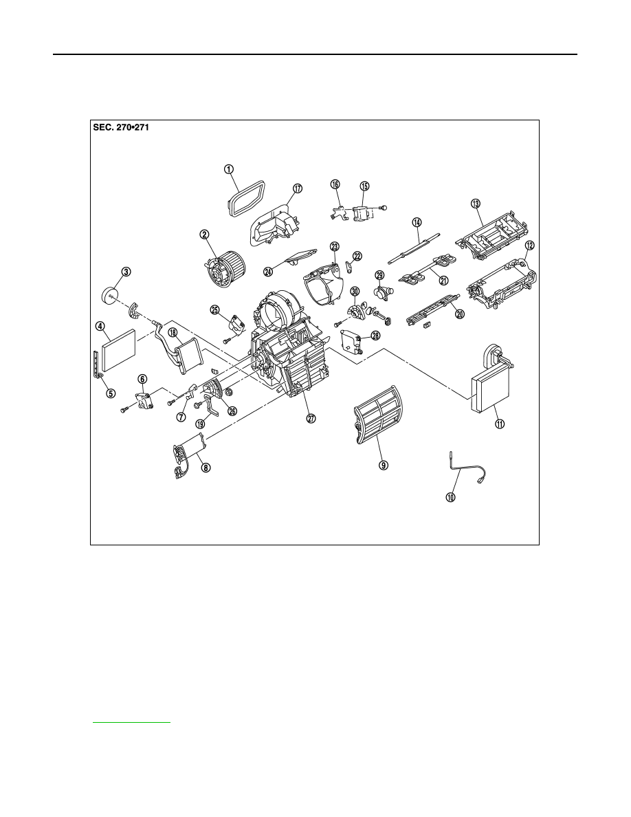
Exploded View
INFOID:0000000001093720
Removal and Installation
INFOID:0000000001093721
REMOVAL
1.
Intake connector seal
2.
Blower motor assembly
3.
Heater pipe seal
4.
Air conditioner filter
5.
Air conditioner filter cover
6.
Air mix door motor (left)
7.
Air mix door lever
8.
Electrical heater
9.
Air mix door (slide door)
10. Intake sensor
11.
Evaporator and expansion valve unit
12.
Center case (lower)
13. Center case (upper)
14.
Defroster door
15.
Intake door motor
16. Intake motor bracket
17.
Intake connector
18.
Heater core
19. Air mix door link bracket
20.
Front ventilator door
21.
Side ventilator door
22. Intake door lever
23.
Intake door box
24.
Intake door
25. Mode door motor
26.
Air mix door link (left)
27.
Heater and cooling unit case
28. Air mix door motor (right)
29.
Aspirator
30.
Air mix door link (right)
*
With left and right ventilation temperature separately system.
for symbols in the figure.
E1IIA0008GB
Нет комментариевНе стесняйтесь поделиться с нами вашим ценным мнением.
Текст